
Intervertebral disc replacement prosthesis

a technology for intervertebral discs and prostheses, which is applied in the field of intervertebral disc replacement prostheses, can solve the problems of pain or neurological deficit, premature degeneration, and tendency to increase the risk of adjacent disc failure, so as to avoid premature degeneration and reduce symptoms

Inactive Publication Date: 2005-11-15
VANDERBILT UNIV
View PDF25 Cites 327 Cited by
  • Summary
  • Abstract
  • Description
  • Claims
  • Application Information

AI Technical Summary

Benefits of technology

The present invention provides an intervertebral disc prosthesis that can alleviate the symptoms of degenerative disc disease without compromising the health of adjacent discs. The prosthesis performs effectively and efficiently within a patient's spine over a long period of time. It is easily implanted and mimics the motion and stiffness of a normal disc. The prosthesis comprises a flexible element enclosing supports that can accommodate a range of disc space geometries for the cervical, thoracic or lumbar spine. The prosthesis also includes a lower and upper disc support within an axial cavity that communicates with one another to provide support to the disc.

Problems solved by technology

Any or a combination of these findings can lead to pain or neurological deficit.
While immobilization and a successful fusion may relieve the pain associated with nerve impingement, the long-term consequences of eliminating the motion of the IVD show a tendency toward increased risk of failure of the adjacent discs.
The lack of motion at the fusion site places increased biomechanical demands on the adjacent discs causing them to degenerate prematurely.
However these devices are devoid of stiffness and stability and rely on the remaining spinal elements, such as the ligaments, muscles and remaining IVD tissue, namely the annulus fibrosis, for stability.
But there is risk of altering the spine's biomechanics by increasing the disc height past the normal range and risk of damage to the annulus fibrosis.
If the disc space is not stretched enough an unstable spinal segment could result, possibly leading to pain and further injury.
Perfect alignment after insertion could be difficult.
Therefore, these prostheses would either bottom out under axial loads and offer no response to bending loads, or be stiff enough to support the axial loads and thereby too stiff to flex under bending loads.

Method used


Image

  • Intervertebral disc replacement prosthesis
  • Intervertebral disc replacement prosthesis
  • Intervertebral disc replacement prosthesis

Examples


Embodiment Construction

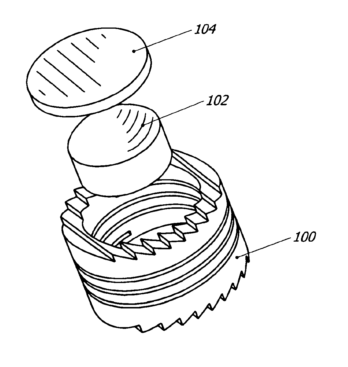
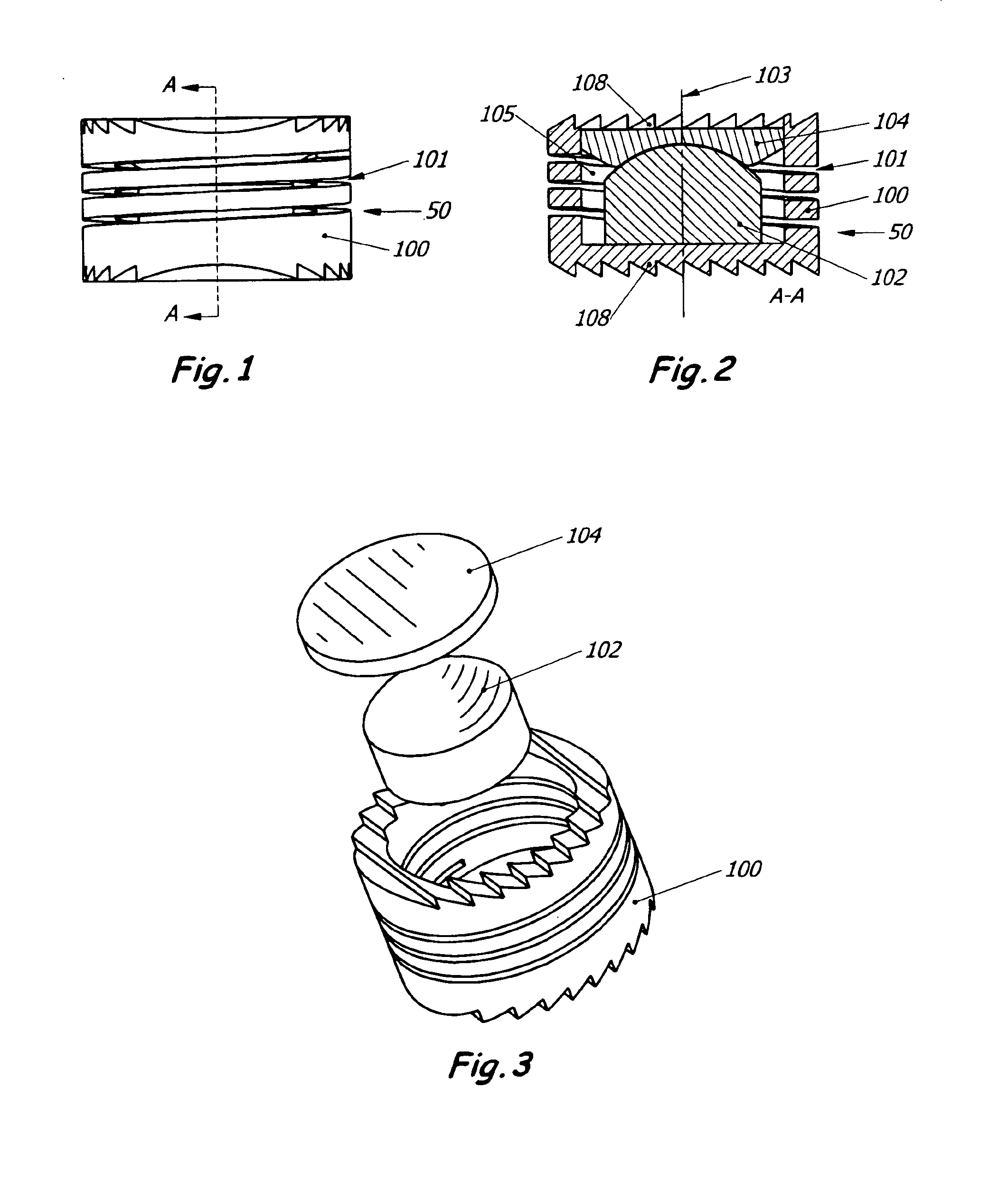
[0031]A preferred embodiment of the invention is shown in FIGS. 1, 2&3. The disc replacement prosthesis of the present invention is an implantable intervertebral disc replacement prosthesis 50 containing a flexure 100 which has an axis 103. The flexure 100 is formed from a solid piece of material in which a blind hole is bored defining an axial cavity 105 which extends along the axis 103. In this embodiment, a helical slit 101 is cut in the perimeter surface, with the axis of the helix approximately coincident with axis 103 of disc member 50, so that the perimeter surface resembles a helical coil or spring.

[0032]The disc replacement of the present embodiment further comprises a lower disc support 102 housed in the axial cavity 105, and an upper disc support 104 housed in the axial cavity 105, with the lower and upper disc supports communicating with one another to provide support to the disc. The lower and upper disc supports also act as bearing elements, and may communicate in a ba...


PUM

PropertyMeasurementUnit
flexibilityaaaaaaaaaa
thicknessaaaaaaaaaa
stiffnessaaaaaaaaaa

Abstract

An intervertebral disc prosthesis that comprises a deformable flexure with an axial cavity, the axial cavity extending along the axis of the flexure, and a slit defined in the perimeter surface of the flexure to provide flexibility to the disc member, the slit having a slit thickness. The slit may be in the form of a coil to impart a spring-like appearance and function. The intervertebral disc prosthesis further comprises a lower disc support housed in the axial cavity and an upper disc support housed in the axial cavity; with the lower and upper disc supports communicating with one another to provide support to the disc. The lower or upper disc support may alternatively be incorporated into the flexure.

Description

[0001]This Application is a Continuation-In-Part of U.S. application Ser. No. 09 / 572,057, now U.S. Pat. No. 6,579,321 B1 filed May 17, 2000, the contents of which are incorporated herein by reference in its entirety. Ser. No. 09 / 572,057 claims priority to Provisional Application No. 60 / 134,500, filed May 17, 1999, now abandoned, the contents of which are incorporated herein by reference.FIELD OF THE INVENTION[0002]This invention relates, generally, to the field of intervertebral disc replacement prosthesis.BACKGROUND OF THE INVENTION AND DESCRIPTION OF RELATED ART[0003]Degenerative disc disease is a common condition of the intervertebral disc (IVD) of the spine characterized by disc height collapse with or without disc herniation, osteophyte formation, foramenal stenosis, facet hypertrophy, synovial cyst, and other symptoms. Any or a combination of these findings can lead to pain or neurological deficit. Many of the symptoms of degenerative disc disease may be alleviated by decompre...

Claims


Application Information

Patent Timeline
Patent Type & Authority Patents(United States)
IPC IPC(8): A61F2/44A61F2/00A61F2/30
CPCA61F2/442A61F2/30744A61F2/30767A61F2002/30113A61F2002/30125A61F2002/30133A61F2002/30225A61F2002/30227A61F2002/30228A61F2002/30233A61F2002/30242A61F2002/30289A61F2002/30405A61F2002/30451A61F2002/30492A61F2002/30507A61F2002/30565A61F2002/30571A61F2002/30596A61F2002/30769A61F2002/30772A61F2002/30795A61F2002/30841A61F2002/30906A61F2002/30909A61F2002/30968A61F2002/30975A61F2002/443A61F2220/0025A61F2220/0058A61F2230/0006A61F2230/0008A61F2230/0015A61F2230/0069A61F2230/0071A61F2230/0091A61F2310/00017A61F2310/00023A61F2310/00029A61F2310/00179A61F2310/00592A61F2002/30594
Inventor GORDON, JEFFREY D.
Owner VANDERBILT UNIV
Learn More