Method and apparatus of calibrating multi-position SLM elements

a multi-position slm element and calibrating technology, applied in the direction of photomechanical equipment, instruments, material analysis by optical means, etc., can solve the problems of limited line width and accuracy of printed patterns on workpieces, limited resolution and accuracy available for optical imaging, etc., to improve the accuracy of image features, increase the accuracy of said image features, and efficiently utilize the effect of results

Inactive Publication Date: 2005-11-15
MICRONIC LASER SYST AB
View PDF32 Cites 42 Cited by
  • Summary
  • Abstract
  • Description
  • Claims
  • Application Information

AI Technical Summary

Benefits of technology

[0006]Accordingly, it is an object of the present invention to improve the accuracy of images formed using computer controlled SLMs by providing a method for determining the contributions made by the individual elements of a computer controlled SLMs to the formation of images. The accuracy of individual features of an image formed using an SLM results from the contributions made to said features by numerous individual elements of said SLM. Therefore, in order to increase the accuracy of said image features, it is necessary to control the contributions made by said individual elements to said image features. The present invention further provides a method to efficiently utilize the results derived from determining the contributions of said SLM elements, resulting in the formation of improved images.

Problems solved by technology

For example, a problem with SLMs is that the individual elements of a given SLM most probably do not exhibit identical characteristics; e.g., they may have different reflectivity, or they may respond differently to equivalent control signals.
These variations in the characteristics of the individual elements of a computer controlled SLM have limited the resolution and accuracy available for their use in optical imaging; e.g., the production of printed patterns on a workpiece has been limited as to its line width and accuracy.

Method used


Image

  • Method and apparatus of calibrating multi-position SLM elements
  • Method and apparatus of calibrating multi-position SLM elements
  • Method and apparatus of calibrating multi-position SLM elements

Examples


Embodiment Construction

[0019]The following detailed description is made with reference to the figures. Preferred embodiments are described to illustrate the present invention, not to limit its scope, which is defined by the claims. Those of ordinary skill in the art will recognize a variety of equivalent variations on the description that follows.

[0020]A state of the art SLM may have several million modulating elements (i.e., elements) arranged in a 1- or 2-dimensional array or matrix, for example a 512-by-2048 array of elements. The elements of an SLM may be movable micro mirrors, transmissive LCD elements, or may be elements of other similar devices based on gratings effects, interference effects, or may be mechanical elements such as individual shutters. Each SLM element may be set to at least 2 different states.

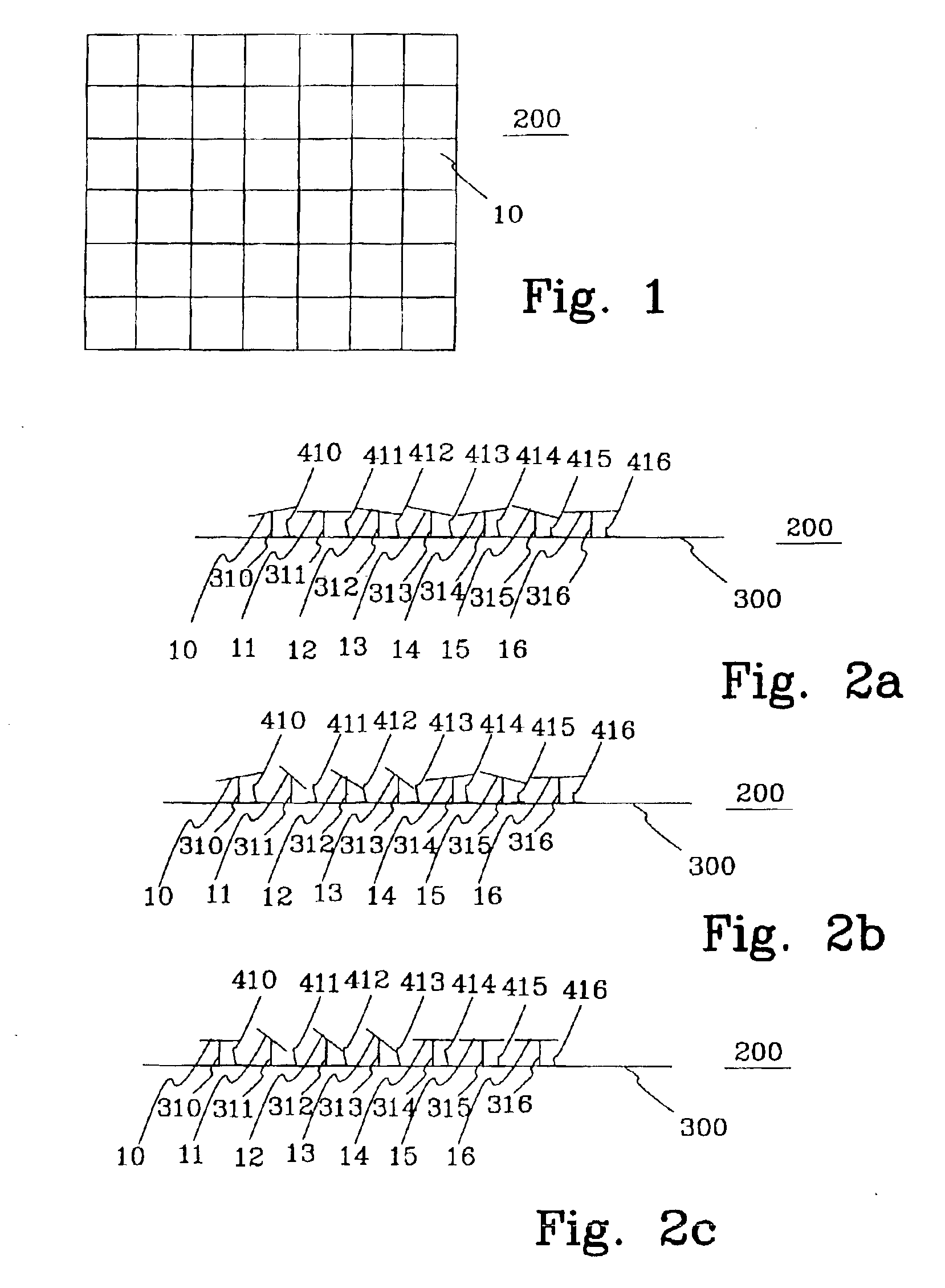
[0021]FIG. 1 illustrates a top view of a section of an array of elements 200 in a spatial light modulator (SLM). FIG. 1 shows elements 10 having an approximately square shape. However, the elem...


PUM

PropertyMeasurementUnit
wavelengthaaaaaaaaaa
electromagneticaaaaaaaaaa
electromagnetic radiationaaaaaaaaaa

Abstract

The present invention relates to a method for calibrating elements in a spatial light modulator (SLM) as a function of an applied element control signal. A plurality of elements are calibrated simultaneously. A beam of electromagnetic radiation is projected onto at least a part of the SLM. An image of said part of said SLM is formed on a device for measuring intensity of electromagnetic radiation. Element calibrating data is generated by using the intensity data as a function of the applied element control signal by either driving a sub-matrix comprising at least two elements out of said part of the SLM to a sequence of applied element control signals or by seeking out the control signal for each element which give the same predetermined intensity value on the device for measuring the intensity of electromagnetic radiation and stepping through N different predetermined intensity values. The invention also relates to an apparatus for patterning a workpiece having such a calibration method. Other aspects of the present invention are reflected in the detailed description.

Description

PRIORITY CLAIM[0001]This application claims the benefit of Provisional Application No. 60 / 323,017 filed 12 Sep. 2001 entitled IMPROVED METHOD AND APPARATUS USING AN SLM, invented by Torbjorn Sandström and Jarek Luberek, which is hereby incorporated by reference.BACKGROUND OF THE INVENTION[0002]Lithographic production is useful for integrated circuits, masks, reticles, flat panel displays, micro-mechanical or micro-optical devices and packaging devices, e.g. lead frames and MCMs. Lithographic production may involve an optical system to image a master pattern onto a workpiece from a spatial light modulator (herein, “SLM”) controlled by a computer. A suitable workpiece may comprise a layer sensitive to electromagnetic radiation, for example visible or non-visible light.[0003]Said computer controlled SLM may be a spatial light modulator (SLM) comprising a one or two dimensional array or matrix of reflective movable micro mirrors, a one or two dimensional array or matrix of transmissive ...

Claims


Application Information

Patent Timeline
Patent Type & Authority Patents(United States)
IPC IPC(8): G02B26/08G02B27/46G03F7/20
CPCG02B26/0841G02B27/46G03F7/70291G02B26/00
Inventor SANDSTROM, TORBJORNLUBEREK, JAREK
Owner MICRONIC LASER SYST AB
Why Eureka
Try Eureka