Coreless current sensor

a current sensor and coreless technology, applied in the direction of instruments, measurement using dc-ac conversion, base element modification, etc., can solve the problems of large coil winding cost, affecting the overall magnetic permeability of the core, and the output signal is affected, and achieves low cost, large signal output, and easy installation.

Inactive Publication Date: 2005-11-15
GRID2020
View PDF7 Cites 53 Cited by
  • Summary
  • Abstract
  • Description
  • Claims
  • Application Information

AI Technical Summary

Benefits of technology

[0011]It is an object of the present invention to provide a current sensor which is easily installed around an existing conductor without disconnecting the conductor. It is a further object of the present invention to provide a current sensor which can accommodate a range of different conductor sizes. I

Problems solved by technology

There are a number of drawbacks to this kind of current sensor.
While such a sensor may be suitable for permanent installations, the need to string the conductor through the core can cause difficulties when retrofitting is required.
The problem with this is that the overall magnetic permeability of the core, and therefore the output signal, is affected by small variations in the gaps where the two halves of the split core meet.
Coil winding adds significantly to the cost of such a sensor.
This cost is higher if more turns are required, and can be especially high if uniform winding is necessary.
The winding of toroidal coils is especially expensive, particularly if a high-level of uniformity is required.
This limits the range of conductor sizes that are suitable for use with this sensor.
Also, there is a problematic trade-off between signal strength and the cost of the coils.
If the coils have few turns, they can be made relatively inexpensively, however, the signal output is then very weak.
The signal output can be greatly increased by increasing the number turns, but this greatly increases the cost because a greater number of turns makes it more difficult to maintain a uniform winding.
If the winding is not uniform, then the sensor is more sensitive to the position of the AC conductor, and to external fields and this can lead to increased signal error.
Even if the coils are perfectly wound for this geometry, there will be some sensitivity to these sources of error, because four linear coils do not form a true toroid.
Whil

Method used


Image

  • Coreless current sensor
  • Coreless current sensor
  • Coreless current sensor

Examples


Embodiment Construction

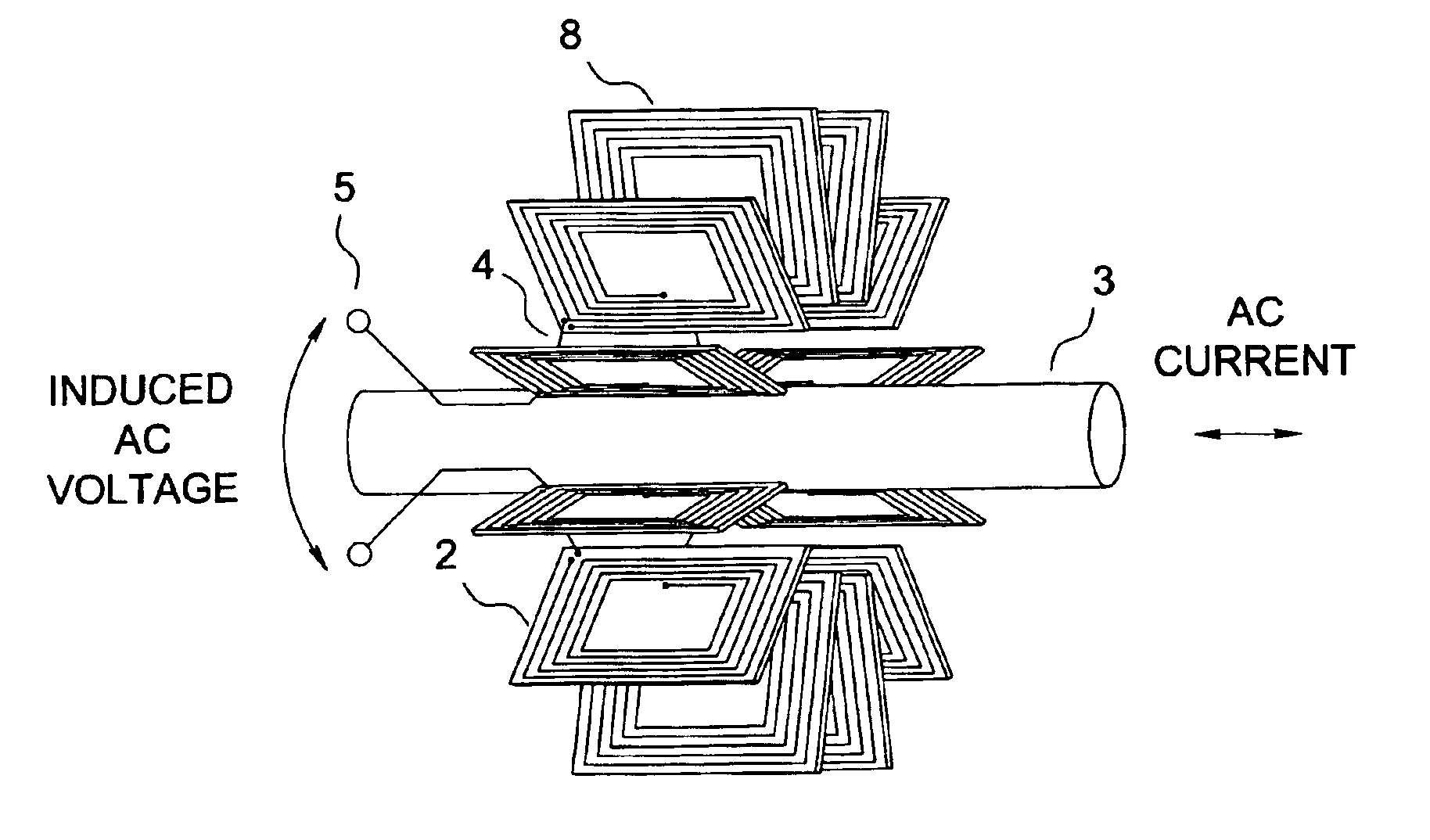
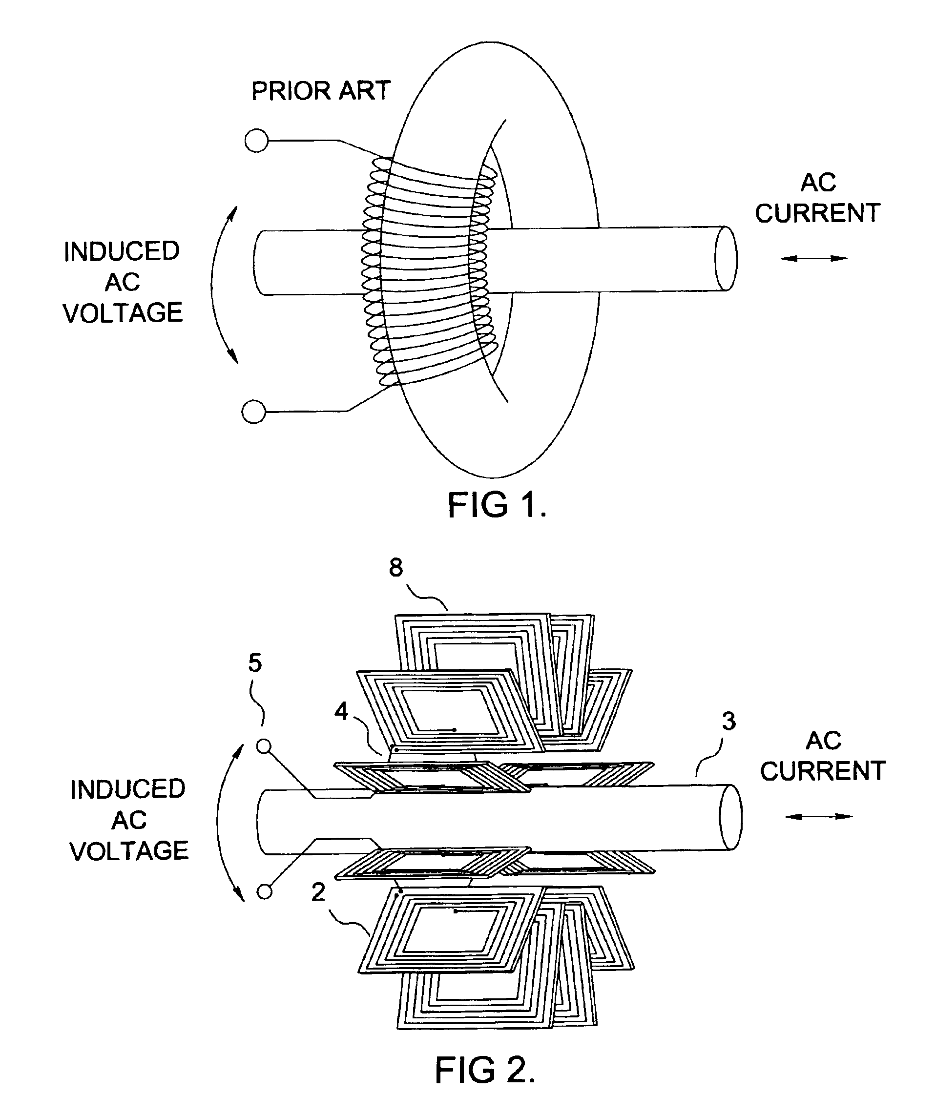
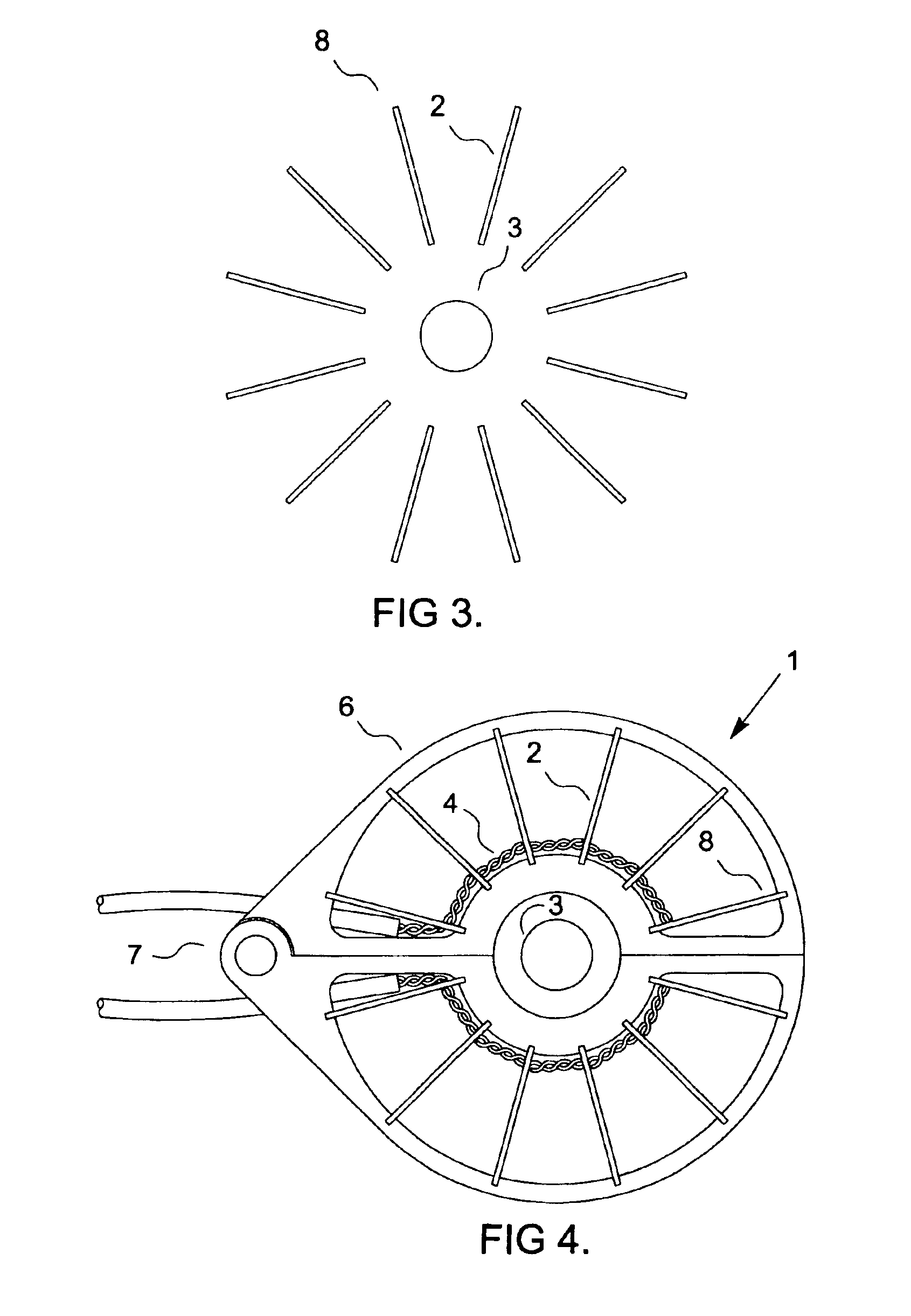
[0030]Referring now to FIG. 2, a plurality of surface coils 2 is arranged around a central cavity for receiving an AC current carrying conductor 3. For simplicity of manufacture, each coil 2 may be printed onto a circuit board 8 or other suitable substrate. Preferably the coils 2 are substantially equally or at least uniformly spaced.

[0031]Although optimum results may be obtained with equal spacing, near optimum results can be achieved with unequal spacing as long as the spacing is uniform. For example, a sensor with 18 surface coils with a spacing of 20 degrees between adjacent coils would be equally and uniformly spaced, but if the spacing alternated between 10 degrees and 30 degrees, e.g. 10,30,10,30 . . . the coils would not be equally spaced, but would still be uniformly spaced. To better understand why, one could imagine two sets of equally spaced coils being interleaved. Each set would possess the benefits of a toroidal geometry, and therefore would possess the same in combin...


PUM


Abstract

A time varying current sensor is constructed using surface coils uniformly spaced around a central cavity adapted to receive the conductor through which the current to be measured flows. Accurate and uniform coil geometry is achieved using printed circuit board technology, thereby eliminating the high cost of precision toroidal coil winding. An optional hinge in the housing can allow the sensor to be easily installed on existing conductors without the need to disconnect and reconnect.

Description

FIELD OF THE INVENTION[0001]This invention relates to the measurement of time-varying electric currents, and more particularly to a coreless current sensor constructed using surface coils.BACKGROUND OF THE INVENTION[0002]In the prior art toroidal current transformers are well established as a method of measuring alternating currents. Referring now to FIG. 1, these devices typically consist of a toroidal ferromagnetic core and a coil. The coil, consisting of insulated copper wire, is wound around the core, usually in a way that conforms to the toroidal shape of the core. Alternating current in a conductor which passes through the center of the core creates a changing magnetic field which in turn induces a voltage at the coil terminals. This voltage provides a measure of the current in the conductor. If high accuracy is required or if the frequency is not constant, this voltage can be integrated by an analog integrator to give a more accurate measure of the current.[0003]In theory if ...

Claims


Application Information

Patent Timeline
IPC IPC(8): G01R15/14G01R15/18G01R19/00G01R33/00
CPCG01R15/186G01R15/181
Inventor DE BUDA, ERIC GEORGE
Owner GRID2020
Why Eureka
Try Eureka