Technique for sensing the rotational speed and angular position of a rotating wheel using a variable threshold

a technology of rotating wheel and threshold, which is applied in the direction of testing/calibration of speed/acceleration/shock measurement devices, devices using electric/magnetic means, galvano-magnetic hall-effect devices, etc., can solve the problem of large measurement error caused by the minimum digital resolution of the lsb, and the inability to accurately measure the rotational speed and angular position. the problem of thermal noise is often noticeable, and the measurement error caused by the minimum digital resolution

a technology of rotating wheel and threshold, which is applied in the direction of testing/calibration of speed/acceleration/shock measurement devices, devices using electric/magnetic means, galvano-magnetic hall-effect devices, etc., can solve the problem of large measurement error caused by the minimum digital resolution of the lsb, and the inability to accurately measure the rotational speed and angular position. the problem of thermal noise is often noticeable, and the measurement error caused by the minimum digital resolution

US6965227B2Inactive Publication Date: 2005-11-15MICRONAS

Image

  • Technique for sensing the rotational speed and angular position of a rotating wheel using a variable threshold
  • Technique for sensing the rotational speed and angular position of a rotating wheel using a variable threshold
  • Technique for sensing the rotational speed and angular position of a rotating wheel using a variable threshold

Examples


Embodiment Construction

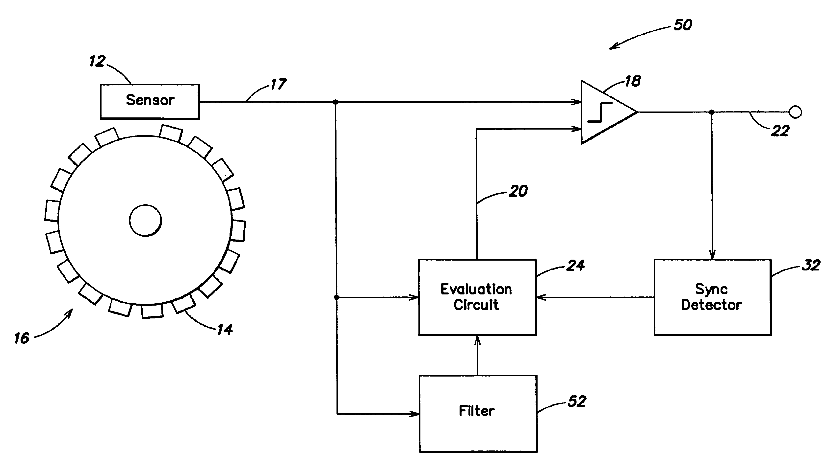
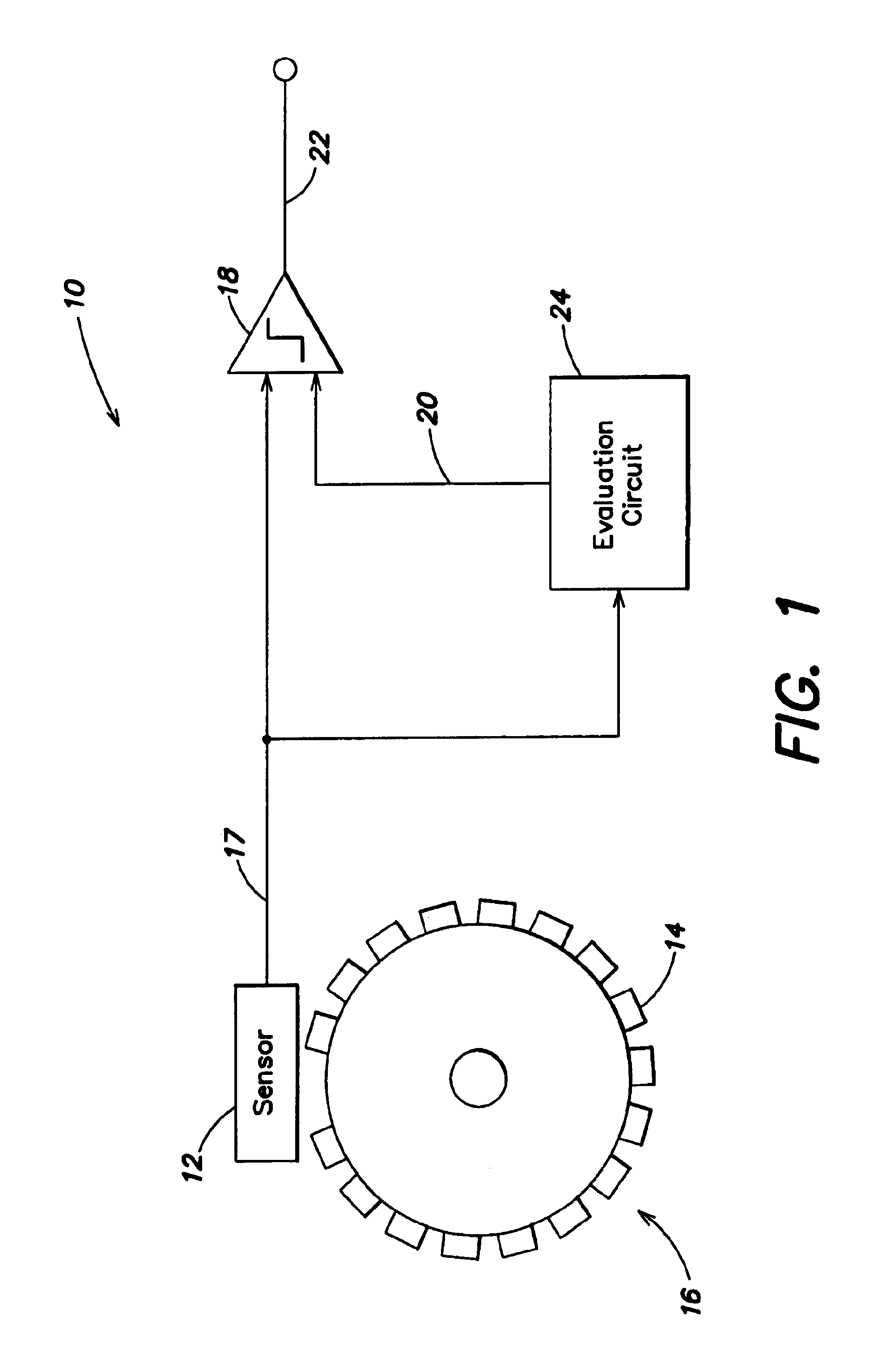
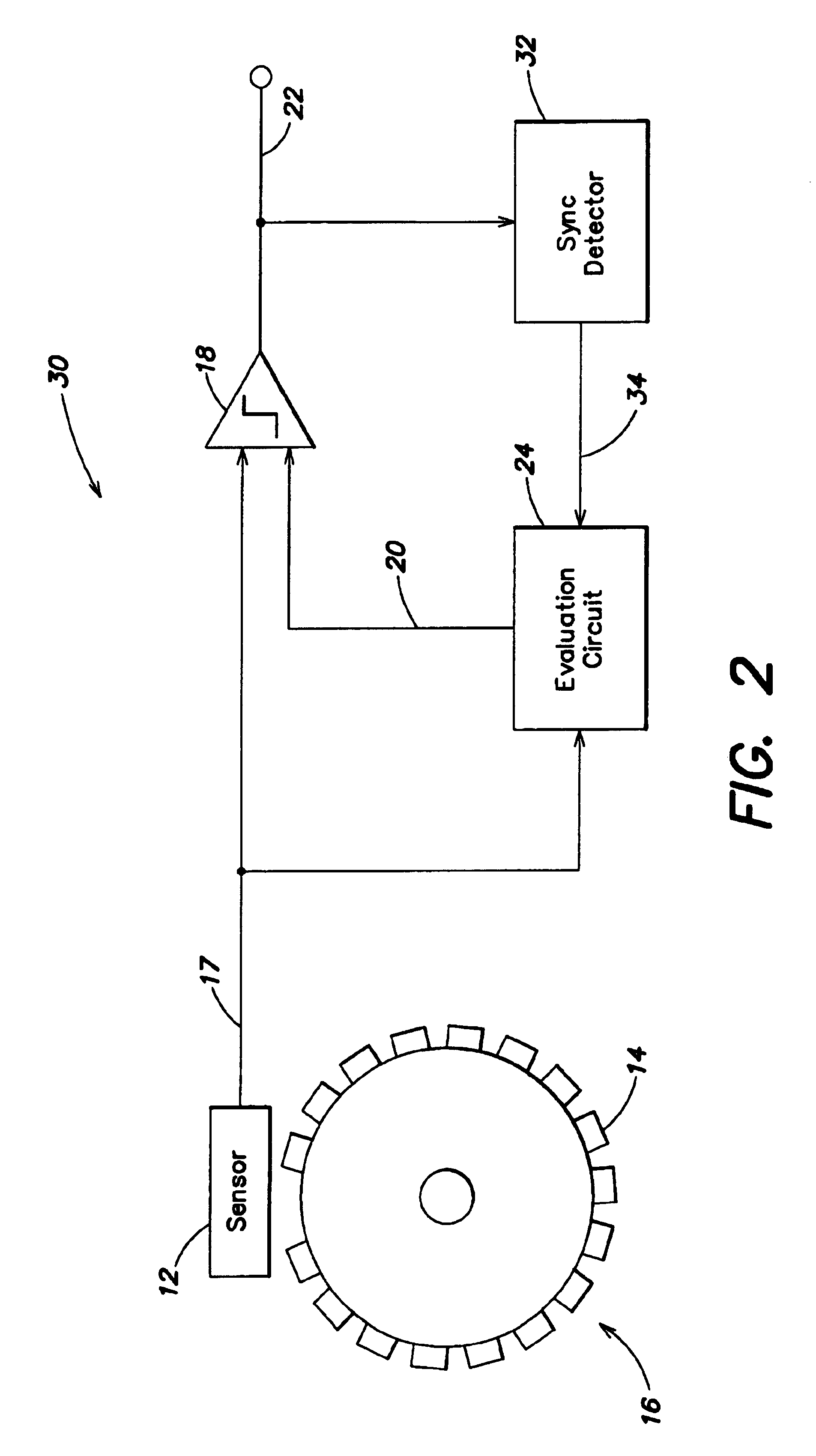
[0023]FIG. 1 illustrates a rotational sensor system 10, which includes a sensor 12 that reads scan marks 14 on a rotating wheel 16, and provides a sensor output signal on a line 17. The sensor output signal is input to a comparator 18, which also receives a first threshold signal on a line 20, and provides a rotational sensing output signal on a line 22.

[0024]The sensor scans the scan marks on the wheel. These scan marks can be lines that are scanned (i.e., read) by an optical sensor, or they can be teeth that are scanned by a Hall sensor. The synchronization mark can be a broad line, a missing tooth, or a broad tooth. When scanning a scan mark—a line or a tooth or a tooth gap, the sensor generates a pulse or skips a pulse, for example in the case of a tooth gap. The data read by the sensor are input to an evaluation circuit that determines the relative angular position of the wheel, its instantaneous angular velocity, and / or its angular acceleration.

[0025]According to an aspect of ...


PUM


Abstract

To detect the rotational speed and angular position of a rotating wheel, a non-contact sensor (e.g., an optical sensor or a Hall sensor) scans scan marks on the wheel, and generates a pulse train. The amplitude of the pulses is compared in a comparator with a variable switching threshold. To achieve accurate measurement results, and to compensate for offset and long-term drift of the sensor, the switching threshold is adjusted if one or more of the following conditions is met: (i) the difference between the pulse amplitude and the switching threshold exceeds a fixable first maximum, (ii) the difference of the amplitudes of two successive pulses exceeds a fixable second maximum, (iii) the difference of the frequencies of successive pulses exceeds a fixable third maximum. The method is particularly advantageous in a motor vehicle, to detect the rotational speed and angular position for an electronic ignition system, or the rotational speed and angular position of the wheels for an ABS braking system, an anti-skid system, or a vehicle stabilization system.

Description

BACKGROUND OF THE INVENTION[0001]The invention relates to a technique for detecting the rotational speed (e.g., RPMs) and the angular position of a rotating wheel with a non-contact sensing device.[0002]For electronic control systems in motor vehicles (e.g., an ABS braking system or an electronic ignition system) it is necessary to measure parameters such as rotational speed, the relative angular position of a rotating wheel or the crankshaft and / or their angular acceleration or instantaneous angular velocity. This is often performed by a non-contact sensor (e.g., an optical sensor or a Hall sensor) that scans the rotating wheel or a wheel seated on the crankshaft. The rotating wheel typically includes scan marks (e.g., lines or teeth).[0003]The accuracy of the rotational speed and angular position measurement is often impaired by external noise signals and / or thermal noise. In a measurement of angular position, the thermal noise is often noticeable as jitter. If a digital measureme...

Claims


Application Information

Patent Timeline
15 Nov 2005
Publication
US6965227B2
IPC
G01P3/42; G01P21/00; G01P3/481; G01P21/02; G01P3/489
CPC
G01P3/481; G01P21/02
Inventors
BLOSSFELD, LOTHAR