Wireless LAN antenna and wireless LAN card with the same

a wireless lan and antenna technology, applied in the direction of elongated active element feed, resonant antenna, radiating element structure, etc., can solve the problem of limited height, length, area and the like of the antenna, and the maximum height between the radiation electrode and the ground surface of the antenna is limited, etc. problem, to achieve satisfactory transmission/reception characteristics in the 2.4 ghz and 5 ghz frequency bands

Inactive Publication Date: 2005-11-15
SAMSUNG ELECTRO MECHANICS CO LTD
View PDF12 Cites 15 Cited by
  • Summary
  • Abstract
  • Description
  • Claims
  • Application Information

AI Technical Summary

Benefits of technology

[0016]Another object of the present invention is to provide a dual band wireless LAN antenna, which can realize impedance matching and adjust a resonance frequency by varying only a feeding position without modifying the structure or pattern of the antenna.
[0017]A further object of the present invention is to provide a dual band wireless LAN antenna, in which an antenna type can easily vary from a monopole-type antenna to an inverted F-type antenna without varying the pattern shape or structure of the antenna, thus suitably and promptly coping with the variation of sets.

Problems solved by technology

However, if the conventional dual band antenna as shown in FIG. 1 is applied to a wireless LAN, there may be limitations in the height, length, area and the like of the antenna due to the size of the wireless LAN antenna.
Therefore, a maximum height between the radiation electrode and the ground surface of the antenna is limited.
Therefore, in the case of a dual band wireless LAN antenna, satisfactory transmission / reception characteristics cannot be obtained in 2.4 GHz and 5 GHz frequency bands due to the limitations of the height and area of the antenna.
In terms of signal characteristics, there is a problem in that, since a bandwidth in the 2.4 GHz frequency band satisfying a VSWR value equal to or less than two is narrow, antenna characteristics are easily deviated depending on the variation of sets or surrounding environments.
However, in this case, there is a problem in that the size of the antenna increases.
Consequently, it is difficult to apply the antenna to the card-shaped wireless LAN products.

Method used


Image

  • Wireless LAN antenna and wireless LAN card with the same
  • Wireless LAN antenna and wireless LAN card with the same
  • Wireless LAN antenna and wireless LAN card with the same

Examples


Embodiment Construction

[0036]Hereinafter, embodiments of the present invention will be described in detail with reference to the attached drawings.

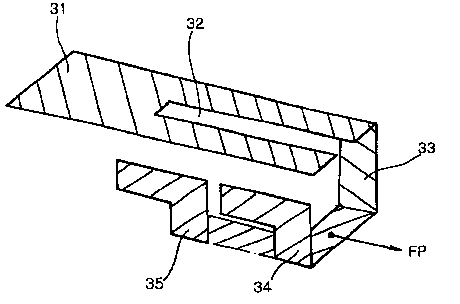
[0037]FIG. 3 is a perspective view of a dual band wireless LAN antenna according to an embodiment of the present invention.

[0038]Referring to FIG. 3, the dual band wireless LAN antenna of the present invention comprises a radiation electrode 31 with a predetermined area for determining at least one transmission / reception frequency band of the antenna, a slot 32 for dividing the radiation electrode 31 to have two current paths connected in parallel from a feeding point FP, a feeding electrode 33 having one end connected to a certain portion of the radiation electrode 31 and having the feeding point FP formed to receive a current at an arbitrary position thereof, and a matching electrode 34 connected to the other end of the feeding electrode 33 and provided with at least one open stub spaced apart from the radiation electrode 31 by a predetermined distance.

[0039]...


PUM


Abstract

A wireless LAN antenna/card which can transmit/receive RF signals in a high frequency band (e.g., 5 GHz) and a low frequency band (e.g., 2.4 GHz), includes a radiation electrode, a matching electrode and a feeding electrode. The radiation electrode has a predetermined area to define a transmission/reception frequency band of the antenna. The matching electrode has at least one open stub. The feeding electrode has a feeding point formed at an arbitrary position of the feeding electrode to receive a current, a first end connected to the radiation electrode, and a second end connected to the matching electrode. Further, the feeding point and a ground point are arbitrarily set on the feeding electrode, thus adjusting the impedance and frequency of the wireless LAN antenna.

Description

BACKGROUND OF THE INVENTION[0001]1. Field of the Invention[0002]The present invention relates generally to antennas provided within a wireless local area network, and more particularly to a wireless local area network antenna and wireless local area network card implemented using the same, which can transmit / receive RF signals in a high frequency band (5 GHz) and a low frequency band (2.4 GHz) without increasing the size of the antenna, and simply adjust antenna characteristics without varying the structure of the antenna.[0003]2. Description of the Related Art[0004]Recently, with the miniaturization and weight reduction of mobile communication devices, and the multiplexing of a transmission / reception band to two or more bands, an antenna, one of important parts for the wireless transmission / reception of a mobile communication terminal, has been developed to an F or inverted F-type antenna from an external helical antenna.[0005]Especially, in the case of a wireless Local Area Networ...

Claims


Application Information

Patent Timeline
Patent Type & Authority Patents(United States)
IPC IPC(8): H01Q5/00H01Q5/01H01Q1/36H01Q1/38H01Q9/04H01Q13/08H01Q9/40H01Q1/24H01Q1/22H01Q5/10H01Q5/364H01Q5/50H01Q9/42
CPCH01Q1/22H01Q1/2275H01Q5/364H01Q1/38H01Q9/42H01Q1/24
Inventor SUNG, JAE SUKPARK, HEE CHAN
Owner SAMSUNG ELECTRO MECHANICS CO LTD
Why Eureka
Try Eureka