Method to correct radial misposition of data tracks

a technology of radial misposition and data track, applied in the field of data storage, can solve the problems of data loss, ineffective existing methods of correcting squeeze and encroachment, and inability to obtain even track spacing, so as to prevent encroachment and degradation, and detect track spacing and squeeze efficiently

Inactive Publication Date: 2005-11-15
MAXTOR
View PDF7 Cites 52 Cited by
  • Summary
  • Abstract
  • Description
  • Claims
  • Application Information

AI Technical Summary

Benefits of technology

[0010]The tracks with improper spacing, indicating they are radially mispositioned (squeeze), are identified and effectively repositioned by adding a squeeze correction term to specific fields in the servo wedges of the tracks to correct for the squeeze. Thereafter, when the disk drive is operating, the servo bursts are used to calculate a position error signal (PES), and the squeeze correction term in the servo fields is combined with the PES to obtain an adjusted PES to position the head such that the reading / writing takes place at a proper track radius. This tells the servo controller how to position the head to write at an adjusted track location (radius) that prevents squeeze.
[0012]The present invention efficiently detects track spacing and squeeze during disk drive manufacturing. Further, the present invention corrects radial position of tracks with improper spacing, or maps out sectors with improper spacing, in order to prevent encroachment and degradation in the OTRC of the disk drive.

Problems solved by technology

However, because of mechanical and electrical limitations, it not possible to obtain even track spacing.
This track mispositioning is referred to as “squeeze” which limits the off-track read capability (OTRC) of the disk drive and can cause encroachment (overwrite) leading to data loss.
Existing methods of correcting squeeze and encroachment are not effective when two adjacent tracks are radially positioned too close to or too far from one another.
This problem is increasingly significant as track densities (measured in tracks-per-inch (TPI)) are increased.
Increased TPI makes track spacing errors and the resulting squeeze more significant to data integrity.
For example, during disk drive manufacturing, a flaw scan test identifies the disk locations which do not provide reliable read and write operations.
However, such techniques are time consuming and expensive.

Method used


Image

  • Method to correct radial misposition of data tracks
  • Method to correct radial misposition of data tracks
  • Method to correct radial misposition of data tracks

Examples


Embodiment Construction

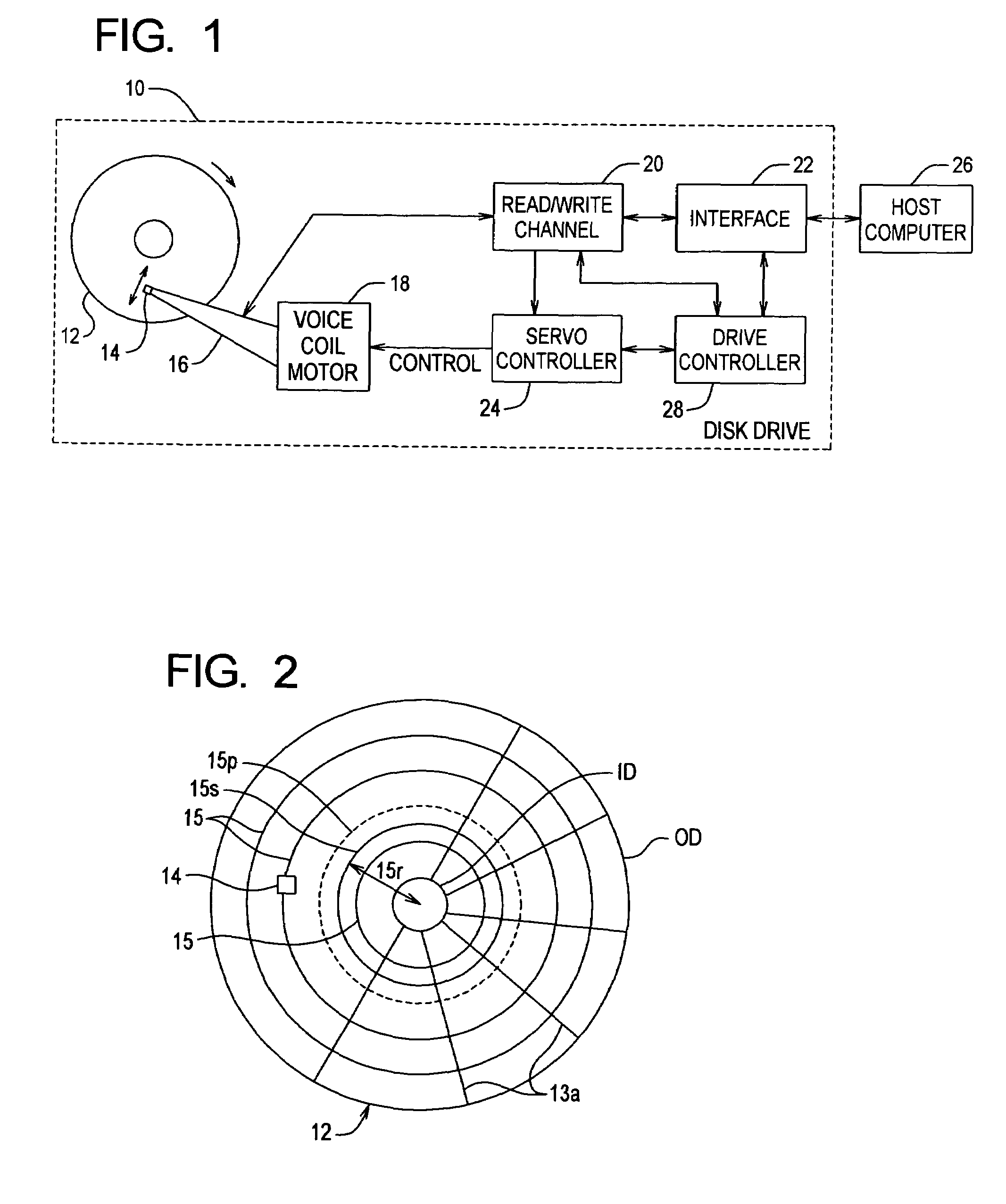
[0034]FIG. 1 is a block diagram illustrating a disk drive 10 in which the present invention can be implemented. The disk drive 10 can be coupled to an external host computer 26 that uses the disk drive 10 as a mass storage device. The disk drive 10 includes functional blocks that do not necessarily represent discrete hardware elements. For example, two or more of the functional blocks can be implemented in firmware in a common digital processor.

[0035]The disk drive 10 includes a data storage disk 12, a transducer head 14, an actuator arm 16, a voice coil motor (VCM) 18, a read / write channel 20, an interface 22, a servo controller 24 and a drive controller 28.

[0036]The disk drive 10 receives read and / or write requests from the host computer 26 and carries out the requests by performing data transfers between the disk 12 and the host computer 26. In a preferred embodiment, the disk drive 10 includes multiple disks 12 in a vertical stack with one head 14 for each operative disk surface...


PUM

PropertyMeasurementUnit
widthaaaaaaaaaa
accelerationaaaaaaaaaa
forceaaaaaaaaaa

Abstract

A disk drive measures the radial misposition of tracks and repositions the tracks at regularly spaced intervals. Written in runout (WRO) in servo bursts is determined to calculate track spacing and squeeze among adjacent tracks. Tracks with improper spacing are repositioned by adding a squeeze correction term to the servo wedges. Thereafter, when the disk drive operates to store data, the servo bursts are used to calculate a position error signal (PES), and the squeeze correction term is combined with the PES to position the head at a proper track radius.

Description

RELATED APPLICATIONS[0001]This application claims priority from U.S. Provisional Application No. 60 / 299,140 filed on Jun. 18, 2001, entitled “Method to Correct Radial Misposition of Data Tracks”, which is incorporated herein by reference.FIELD OF THE INVENTION[0002]The present invention relates in general to data storage, and in particular to improving data storage reliability and efficacy in a disk drive.BACKGROUND OF THE INVENTION[0003]Disk drives are well known in the computer art for providing secondary mass storage with random access. A disk drive comprises one or more magnetic data storage disks rotated on a spindle by a spindle motor within an enclosed housing. A magnetic transducer head is placed on an actuator arm and positioned very closely to a corresponding disk surface by a slider suspended upon an air bearing. Servo information is typically written in servo sectors which are interleaved between data sectors or blocks. Servo information provides a servo controller with ...

Claims


Application Information

Patent Timeline
Patent Type & Authority Patents(United States)
IPC IPC(8): G11B5/596
CPCG11B5/59627
Inventor PERLMUTTER, STEPHENMELROSE, THOMASHARGARTEN, JAMESBRUNNETT, DONLEVY, LLOYDCERDA, ADRIAN
Owner MAXTOR
Why Eureka
Try Eureka