Developing apparatus

a technology of developing apparatus and developing shaft, which is applied in the direction of electrographic process apparatus, instruments, optics, etc., can solve the problems of increasing the amount of torque necessary to drive the developing shaft, affecting the effort to reduce the developing shaft, and difficult to attract the toner by magnetic force, etc., to achieve stable amount, small torque necessary to drive, and simple structure

Inactive Publication Date: 2005-11-15
CANON KK
View PDF13 Cites 16 Cited by
  • Summary
  • Abstract
  • Description
  • Claims
  • Application Information

AI Technical Summary

Benefits of technology

[0018]Another object of the present invention is to provide a developing apparatus which does not contribute to the formation of a defective image such as a streaky image.
[0019]Another object of the present invention is to provide a developing apparatus which does not suffer from the problem that the development potential is affected by the electrical current which flows from the developer supplying member to the developer carrying member.
[0020]Another object of the present invention is to provide a developing apparatus which does not contribute to the formation of a defective image such as a foggy image.
[0021]Another object of the present invention is to provide a developing apparatus which is stable in the amount by which the developer carrying member is supplied with developer.
[0022]Another object or the present invention is to provide a developing apparatus which is capable of uniformly charging the developer on the developer carrying member, in proportion to the sate of discharge from the developer carrying member.
[0023]Another object of the present invention is to provide a developing apparatus which is smaller in the amount of the torque necessary to drive it, is simple in structure, and is smaller in size.

Problems solved by technology

However, in the case of a nonmagnetic single-component development method, the magnetism of the toner is extremely weak, making it difficult to attract the toner by magnetic force.
A development method, such as the one disclosed in the aforementioned Japanese Laid-open Patent Application 6-16210, which employs a stripping-supplying roller 13 as a developer supplying member, was problematic in that there is a difference in peripheral velocity between the development roller 5 and stripping-supplying roller 13, which causes the peripheral surfaces of the two rollers to rub against each other, increasing thereby the amount of the torque necessary to drive the developing apparatus 4.
However, they still require the force necessary to rotationally drive the developer supplying member, being therefore as complicated as the method disclosed in Japanese Laid-open Patent Application 6-16210, from the standpoint of the mechanism for driving the various moving members.
Also in the case of the methods disclosed in Japanese Laid-open Patent Applications 2-101485 and 8-179608, the developer supplying member which has a certain amount of volume is positioned in the adjacencies of the development roller 5, with no contact between the two, adversely affecting the effort to reduce the developing apparatus 4 in size.
Further, as voltage was applied to the developer supplying member in order to supply the development roller 5 with developer, the electric current which flowed from the developer supplying member to the development roller sometimes became nonuniform due to local current leaks, reducing thereby the level of uniformity at which developer was supplied to the development roller.
This nonuniformity in the amount by which developer was supplied sometimes resulted in the formation of a streaky image.

Method used


Image

  • Developing apparatus
  • Developing apparatus
  • Developing apparatus

Examples


embodiment 1

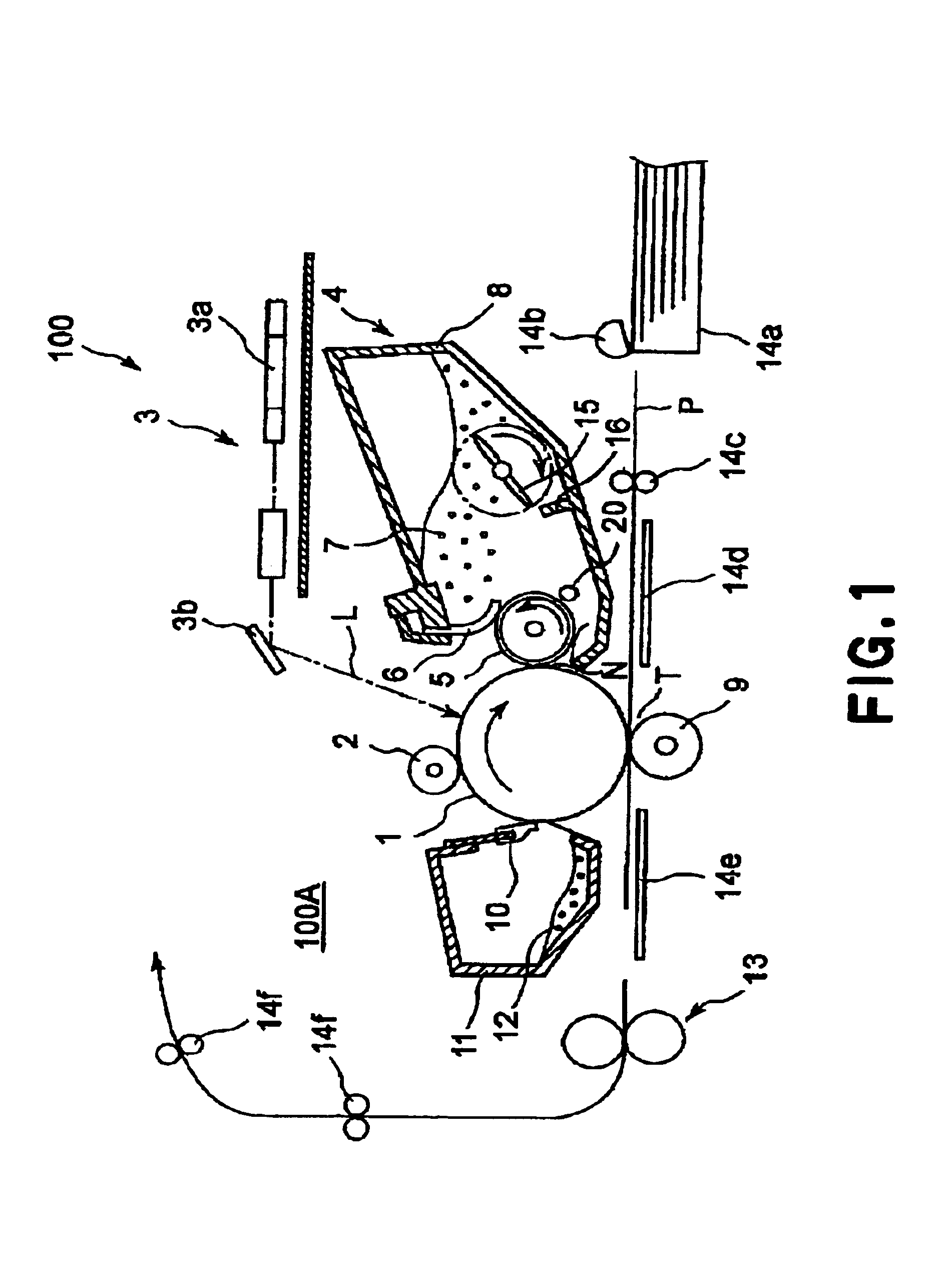
[0040]FIG. 1 is a schematic sectional view of the image forming apparatus in the first embodiment of the present invention. The image forming apparatus 100 in this embodiment is a laser beam printer, which forms an image on recording medium such as a recording paper or OHP sheet, with the use of one of the electrophotographic recording methods, in accordance with the image forming data from an external host, such as a personal computer, an original reading apparatus, etc., connected to the main assembly 100A of the image forming apparatus 100 in a manner to allow information to be exchanged between the two apparatuses.

[0041]First, referring to FIG. 1, the image forming apparatus will be described regarding general structure and operation. The image forming apparatus 100 is provided with an electrophotographic photosensitive member, as an image bearing member 1, which is in the form of a drum (which hereinafter will be referred to as “photosensitive drum 1”). It is also provided with...

embodiment 2

[0161]Next, the image forming apparatus in another embodiment of the present invention will be described. FIG. 12 is a schematic sectional view of an image forming apparatus 200 in accordance with the present invention. In terms of the basic structure and operation, the image forming apparatus 200 in this embodiment is the same as that in the preceding embodiment, except that the process cartridge in this embodiment is removably mountable in the main assembly of the image forming apparatus. Thus, the elements of the image forming apparatus in this embodiment which are the same in structure and operation as those in the first embodiment will be given the same referential symbols as those given in the description of the first embodiment, and will not be described here.

[0162]FIG. 13 is a schematic sectional view of the process cartridge 200B removably mountable in the image forming apparatus 200 in this embodiment. In this embodiment, the process cartridge 200B comprises a cleaning mea...


PUM


Abstract

A developer apparatus includes a developer carrying member, for carrying a developer to a developing portion, the developer carrying member including an electroconductive base and a resistance layer provided thereon; a developer feeding member for being supplied with a voltage to supply the developer to the developer carrying member; wherein a surface moving speed of the developer carrying member Vp [mm/sec], a resistance R1 (Ω) of the developer carrying member when an electric current applied the developer carrying member is 0.04 Vp [μA], and a resistance R2 (Ω) or the developer carrying member when the electric current applied to the developer carrying member is 4 Vp [μA], satisfy:
r1/R2<15.

Description

FIELD OF THE INVENTION AND RELATED ART[0001]The present invention relates to a developing apparatus employed by an electrophotographic or electrostatic image forming apparatus, a process cartridge removably mountable in the main assembly of an image forming apparatus, and the like. Here, an electrophotographic image forming apparatus means a printer, a facsimile machine, a copying machine, etc.[0002]A developing apparatus which uses a nonmagnetic single-component developer to develop an electrostatic latent image into a visible image has been realized. FIG. 14 is a schematic sectional view of a typical developing apparatus in accordance with the prior art which uses a nonmagnetic single-component developer.[0003]Referring to FIG. 14, a developing apparatus 4 has a developer container (toner container) 8 which holds toner 7, for example, dielectric nonmagnetic single-component developer, the inherent electrical polarity of which is negative. The toner 7 contains a yellow, magenta, cy...

Claims


Application Information

Patent Timeline
Patent Type & Authority Patents(United States)
IPC IPC(8): G03G15/08G03G15/06
CPCG03G15/065G03G15/081
Inventor NAKAGAWA, KENOCHI, JUNICHIKAWAMURA, TAKESHI
Owner CANON KK
Why Eureka
Try Eureka