
Fuel drain structure in fuel line

a technology of fuel drain and structure, which is applied in the direction of combustion-air/fuel-air treatment, electric control, machines/engines, etc., can solve problems such as air pollution, and achieve the effect of reducing incomplete combustion of fuel

Inactive Publication Date: 2005-11-22
HYUNDAI MOTOR CO LTD
View PDF10 Cites 5 Cited by
  • Summary
  • Abstract
  • Description
  • Claims
  • Application Information

AI Technical Summary

Benefits of technology

[0004]Embodiments of the present invention provide a fuel drain structure in a fuel line for effectively draining the fuel leftover in the fuel line when the engine ceases moving, thereby preventing the fuel from leaking into a combustion chamber via an injector and thus reducing incomplete combustion of the fuel when the engine is re-started.

Problems solved by technology

In general, when an engine stops running and fuel provided from a fuel pump remains in a fuel line, the fuel tends to flow into the engine via an injector due to pressure increased by high temperature around the engine, which contributes to air pollution by excessive incomplete combustion when the engine gets re-started.

Method used


Image

  • Fuel drain structure in fuel line
  • Fuel drain structure in fuel line
  • Fuel drain structure in fuel line

Examples


Embodiment Construction

[0010]A preferred embodiment of the present invention will now be described in detail with reference to the accompanying drawings.

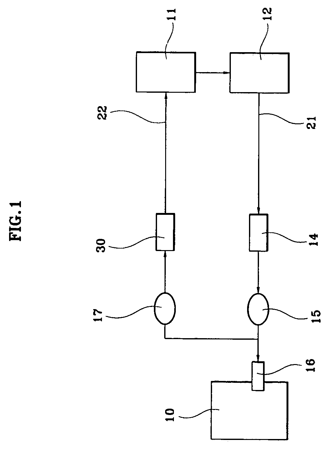
[0011]As shown in FIG. 1, fuel pumped out from a fuel tank 11 via a fuel pump 12 is filtered at a fuel filter and is injected into an intake manifold of an engine 10 through an injector 16. A pressure sensor 17 and a regulator 30 are mounted at a return line 22 for adjusting the fuel pumped from the fuel pump 12 to be injected through the injector 16 to the engine at a constant pressure. A fuel-stopping solenoid valve 14 restricts the fuel from being provided to the injector 16 according to the on / off state of the ignition key, and a temperature sensor 15 measures fuel temperature. Both the fuel-stopping solenoid valve 14 and temperature sensor 15 are mounted at a feed line 21.

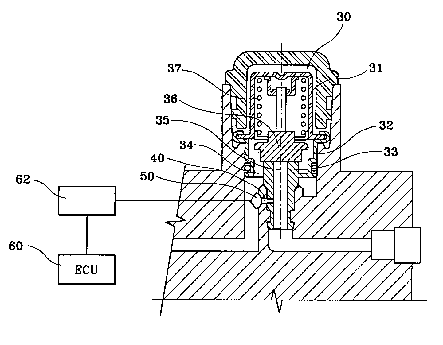
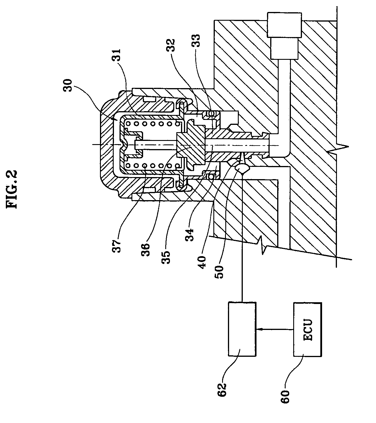
[0012]With reference to FIG. 2, the regulator 30 comprises a housing 31 forming a chamber 32 by coupling with a valve seat 33. A fuel inlet 34 is at one side of the chamber 32 for a...


PUM


Abstract

A fuel drain structure in a fuel line comprising a bypass channel for connecting a fuel influx side and a fuel efflux side of a regulator, and a rotary valve for opening and closing the bypass channel, contributing to a prevention of fuel remaining in the fuel line from entering the engine when the engine stops running, and minimization of pollution occurring when the engine is re-started.

Description

CROSS-REFERENCE TO RELATED APPLICATIONS[0001]This application claims priority of Korean Application No. 10-2003-0019344, filed on Mar. 28, 2003.FIELD OF THE INVENTION[0002]The present invention relates to a fuel drain structure in a fuel line, and more particularly to a drain structure for draining fuel from the line when the engine stops running.BACKGROUND OF THE INVENTION[0003]In general, when an engine stops running and fuel provided from a fuel pump remains in a fuel line, the fuel tends to flow into the engine via an injector due to pressure increased by high temperature around the engine, which contributes to air pollution by excessive incomplete combustion when the engine gets re-started.SUMMARY OF THE INVENTION[0004]Embodiments of the present invention provide a fuel drain structure in a fuel line for effectively draining the fuel leftover in the fuel line when the engine ceases moving, thereby preventing the fuel from leaking into a combustion chamber via an injector and th...

Claims


Application Information

Patent Timeline
Patent Type & Authority Patents(United States)
IPC IPC(8): F02M69/00F02M55/02F02D41/06F02M55/00F02M37/04F02M33/00F02M37/00F02M33/08F02M69/28F02M69/54
CPCF02M55/00F02M69/28F02M69/54F02M37/00
Inventor SHIN, CHANG-HYUN
Owner HYUNDAI MOTOR CO LTD
Learn More