Autobalance roping and drive arrangement

a technology of roping and driving arrangement, which is applied in the direction of elevators, transportation and packaging, building lifts, etc., can solve the problems of affecting the balance of the cab and counterweight, presenting stresses on the drive motor, and the potential for fluid leakage and loud noises produced by chain movement, so as to reduce the load on the drive motor and less of an opportunity for motor overload. , the effect of reducing the horsepower requirements of the motor

Inactive Publication Date: 2005-11-22
THYSSENKRUPP ELEVATOR AG (DE)
View PDF16 Cites 13 Cited by
  • Summary
  • Abstract
  • Description
  • Claims
  • Application Information

AI Technical Summary

Benefits of technology

[0007]The claimed invention addresses these problems associated with prior art elevators. The claimed invention allows for adjustments to be made to an elevator system comprising a cab and counterweight such that the weight of the cab and the weight of the counterweight are continuously in a state of balance. The invention reduces the load on a drive motor in the elevator in that the motor is always driving a balanced cab and counterweight system. Because the cab and counterweight are continuously kept in a state of balance, there is less of an opportunity for motor overload and the horsepower requirements for the motor are lessened, thereby permitting the use of smaller or lighter motors.

Problems solved by technology

There are certain problems in attempting to balance the weight of an elevator cab with a counterweight.
Therefore, the cab and counterweight will not always be in balance.
This condition presents stresses on the drive motor.
However, this system has drawbacks such as the potential for fluid leakage and loud noises produced by chain movement.

Method used


Image

  • Autobalance roping and drive arrangement
  • Autobalance roping and drive arrangement

Examples


Embodiment Construction

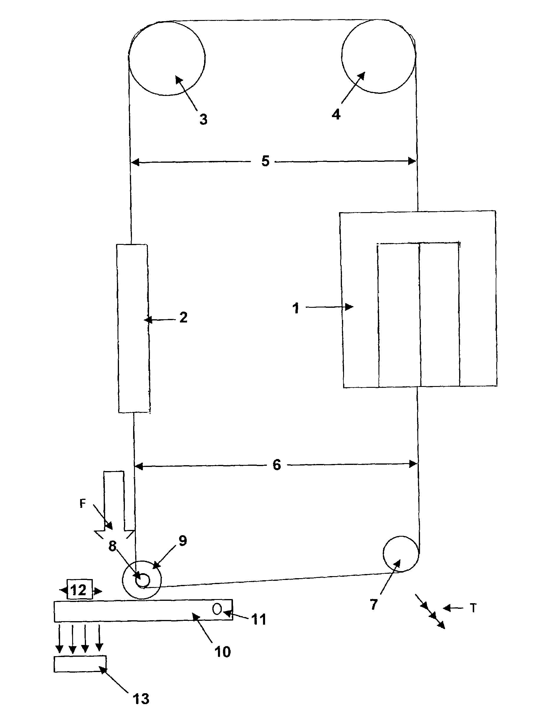
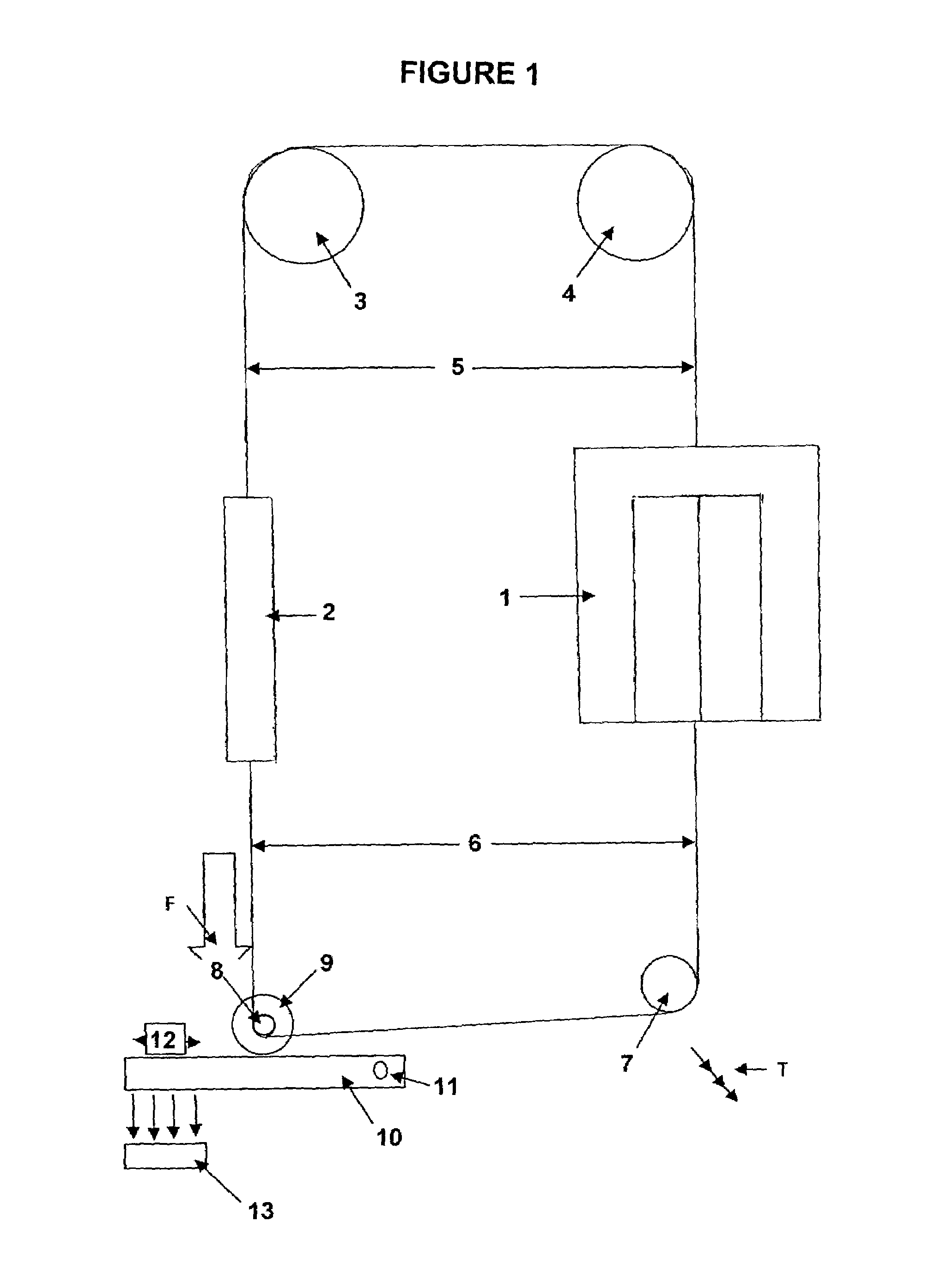
[0024]An embodiment of the claimed invention will now be described with reference to FIG. 1. FIG. 1 shows elevator system comprising a cab 1 and a counterweight 2 located in a hoistway (not shown). The suspension sheave section is located at the top of the elevator hoistway and in this embodiment comprises two suspension sheaves 3 and 4. The top sides of cab 1 and the counterweight 2 are connected to opposite ends of a suspension rope 5, which is routed by the suspension sheaves 3 and 4. The suspension sheaves 3 and 4 guide the suspension rope 5, and do not have a traction drive component. The bottoms sides of the cab 1 and counterweight 2 are connected to opposite ends of a drive rope 6, which is routed by the deflector sheave 7 and drive sheave 8. The deflector sheave 7 and drive sheave 8 are located below the elevator cab 1 and counterweight 2. A motor 9 is connected to the drive sheave 8, which is used to move the cab 1 and the counterweight 2 in the hoistway.

[0025]In this embod...


PUM


Abstract

An autobalancing roping and drive arrangement for elevators which continuously balances the weight of an elevator cab and the weight of a counterweight such that the force on the drive motor necessary to move the cab from floor to floor is minimized. A weighting device connected to a drive sheave imparts a downward force on the drive sheave and creates a tension in a force section, causing traction contact between the drive sheave and the drive rope. The tension in the force section includes a downward vertical component of force. This component and the weight of the counterweight combine to create a downward force on one side of the suspension sheave section. The downward force balances the downward force created by the weight of the cab on the opposite side of the suspension sheave section. The tension in the force section automatically compensates for the difference in weight between the cab and the counterweight and thereby maintains the elevator in balance.

Description

FIELD OF THE INVENTION[0001]The claimed invention is directed to the field of elevator technology. More specifically, the invention is directed to an autobalancing roping and drive arrangement for elevators which continuously balances the weight of an elevator cab and the weight of a counterweight such that the force necessary to move the cab from floor to floor is minimized.BACKGROUND OF THE INVENTION[0002]Traction elevator systems typically comprise an elevator cab, a counterweight, and one or more sheaves from which the cab and counterweight are suspended. The counterweight typically weighs about the same as the elevator cab when the cab is filled to about 40% capacity.[0003]There are certain problems in attempting to balance the weight of an elevator cab with a counterweight. For example, the counterweight typically has a static, non-varying weight, whereas the cab will always have a variable load. Therefore, the cab and counterweight will not always be in balance. This conditio...

Claims


Application Information

Patent Timeline
Patent Type & Authority Patents(United States)
IPC IPC(8): B66B7/06
CPCB66B7/068B66B11/009
Inventor SWEET, ROBERT H.
Owner THYSSENKRUPP ELEVATOR AG (DE)
Why Eureka
Try Eureka