Occupant detecting apparatus capable of improving detection accuracy

Inactive Publication Date: 2005-11-22
HONDA ELESYS CO LTD
View PDF18 Cites 6 Cited by
  • Summary
  • Abstract
  • Description
  • Claims
  • Application Information

AI Technical Summary

Benefits of technology

[0013]It is an object of the present invention to provide an occupant detecting apparatus capable of improving the detection accuracy.

Problems solved by technology

Note that, when a child or an infant is seated on the front passenger seat, if the airbag is inflated, the face of the child or infant is damaged by the inflation of the airbag, which invites a more serious result.
Therefore, when a child or an infant is seated on the front passenger seat, the inflation of the airbag is not permissible.
In the above-described second prior art occupant detecting apparatus, however, the electric field sensors detect a wet seat with no occupant as a human body to permit the inflation of the airbag.
Thus, both of the first and second prior art occupant detecting apparatuses are inferior in the detection accuracy.

Method used


Image

  • Occupant detecting apparatus capable of improving detection accuracy
  • Occupant detecting apparatus capable of improving detection accuracy
  • Occupant detecting apparatus capable of improving detection accuracy

Examples


first embodiment

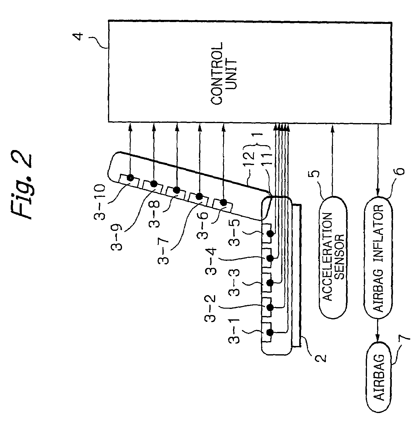
[0044]In FIG. 2, which illustrates the occupant detecting apparatus according to the present invention, reference numeral 1 designates a front passenger seat formed by a bottom part 11 and a rear part 12.

[0045]A load sensor 2 formed by a strain gauge or a pressure sensor is provided between the bottom part 11 of the seat 1 and a vehicle floor (not shown), to measure the weight of an occupant seated on the seat 1.

[0046]Five antenna electrodes 3-1, 3-2, 3-3, 3-4 and 3-5 for electric field sensors are provided in the bottom part 11 of the seat 1, and five antenna electrodes 3-6, 3-7, 3-8, 3-9 and 3-10 for electric field sensors are provided in the rear part 12 of the seat 1.

[0047]The load sensor 2 and the antenna electrodes 3-1, 3-2, . . . , 3-10 are connected by a wire harness to a control unit 4 which also receives an output signal from an acceleration sensor 5 to control an airbag inflator 6 for inflating an airbag. For example, the inflator 6 includes a source of gun powder, an ign...

second embodiment

[0086]In FIG. 8, which illustrates the occupant detecting apparatus according to the present invention, only the antenna electrode 3-10 is provided in the rear part 12 of the seat 1. In this case, the antenna electrode 3-10 is used for determining whether or not an object seated on the seat 1 is higher than a predetermined value. Also, the load sensor 2 of FIG. 2 is not provided.

[0087]In FIG. 9, which is a block circuit diagram of the control unit 4 of FIG. 8, one of the antenna electrodes 3-1, 3-2, . . . , 3-5 and 3-10 is selected by selectors 4-6 and 4-7 and is connected between the resistor 4-3 and the voltage buffer 4-4.

[0088]The airbag inflating operation of the control unit 4 (the CPU 4-11) of FIG. 9 is the same as that as in the flowchart of FIG. 4.

[0089]An operation of calculating the airbag inflating permission flag FX of FIG. 4 is explained next with reference to a routine of FIG. 10 which is carried out at pretermined time intervals.

[0090]First, at step 1001, the CPU 4-11...

third embodiment

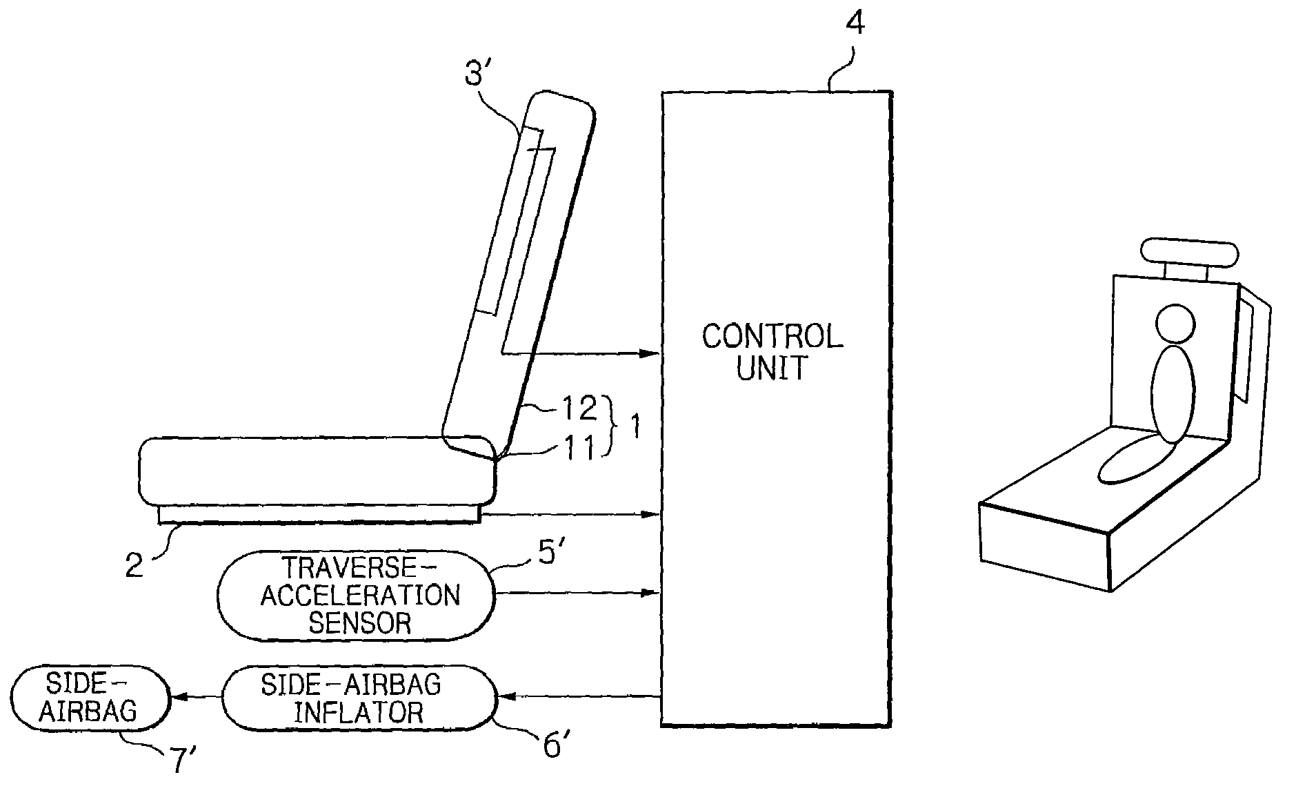
[0107]In FIG. 13, which illustrates the occupant detecting apparatus according to the present invention, reference numeral 1 designates a front passenger seat formed by a bottom part 11 and a rear part 12.

[0108]A load sensor 2 formed by a strain gauge or a pressure sensor is provided between the bottom part 11 of the seat 1 and a vehicle floor (not shown), to measure the weight of an occupant seated on the seat 1.

[0109]An antenna electrode 3′ for an electric field sensor is provided on the side of the rear part 12 of the seat 1.

[0110]The load sensor 2 and the antenna electrode 3′ are connected by wire harness to a control unit 4 which also receives an output signal from a traverse acceleration sensor 5′ to control a side-airbag inflator 6′ for inflating a side-airbag 7′. That is, when the inflator 6′ is driven by the control unit 4, pressurized hot gas is injected into the side-airbag 7′, thus rapidly inflating the side-airbag 7′.

[0111]Note that the side-airbag 7′ is located next to...


PUM


Abstract

In an occupant detecting apparatus for detecting an occupant seated on a passenger seat of a vehicle with an airbag for the occupant, a load sensor is provided in a bottom part of the seat. A plurality of first electric field sensors are provided in the bottom part of the seat, and a plurality of second electric field sensors are provided in a rear part of the seat. An airbag inflating permission control unit permits inflation of the airbag in accordance with output signals of the load sensor and the first and second electric field sensors.

Description

[0001]This application is a Divisional of U.S. patent application Ser. No. 09 / 962,356 filed on Sep. 26, 2001 now U.S. Pat. No. 6,684,973. The entire contents of the above-identified application is hereby incorporated by reference.BACKGROUND OF THE INVENTION[0002]1. Field of the Invention[0003]The present invention relates to an occupant detecting apparatus for detecting an occupant seated on a passenger seat of a vehicle with an airbag.[0004]2. Description of the Related Art[0005]In a vehicle, an airbag is provided in a driver seat in order to alleviate the impact of a collision. Generally, since an adult is seated on the driver seat, when any occupant seated on the driver seat is detected, the inflation of the airbag is always permitted.[0006]On the other hand, an airbag is also provided in a front passenger seat. In this case, since a child or an infant as well as an adult may be seated on the front passenger seat, the permission for the inflation of the airbag depends upon an occ...

Claims


Application Information

Patent Timeline
IPC IPC(8): B60R21/01G01V7/00A47C7/62B60N2/90B60R21/015B60R21/16G01V3/00G01V11/00
CPCB60R21/01532B60R21/01516B60R21/01556B60R21/0152B60R2021/01068
Inventor BABA, SATOSHIJINNO, KAZUNORIOIKAWA, HIROSHISAITO, TAKASHISAITO, NAOKINAGAI, SHINGOMASUDA, YOSHINORI
Owner HONDA ELESYS CO LTD
Why Eureka
Try Eureka