Adaptive geartooth sensor with dual peak detectors and true power on capability

a technology of dual peak detectors and adaptable geartooth sensors, applied in the field of sensor devices, can solve the problems of difficult to achieve high-speed switching points at both low and high rpm, the inability of such systems to accurately detect positions, and the use of a single hall elemen

Active Publication Date: 2005-11-22
HONEYWELL INT INC
View PDF8 Cites 13 Cited by
  • Summary
  • Abstract
  • Description
  • Claims
  • Application Information

AI Technical Summary

Benefits of technology

[0006]It is, therefore, one aspect of the present invention to provide for improved sensor devices, methods and systems.

Problems solved by technology

Many of these types of sensors and related systems are mechanical in nature and are very sensitive to the wearing of contacts, contact contamination, and so forth.
One of the primary problems with this approach is the inability of such systems to accurately detect position.
The accuracy requirement of such systems makes it difficult, for example, to use a single Hall element because of the offset and shifts over temperature.
The difficulty with both Hall and magnetoresistive technologies is that high accuracy switching points at both low and high RPM's are difficult to achieve.

Method used


Image

  • Adaptive geartooth sensor with dual peak detectors and true power on capability
  • Adaptive geartooth sensor with dual peak detectors and true power on capability
  • Adaptive geartooth sensor with dual peak detectors and true power on capability

Examples


Embodiment Construction

[0024]The particular values and configurations discussed in these non-limiting examples can be varied and are cited merely to illustrate at least one embodiment and are not intended to limit the scope of the invention.

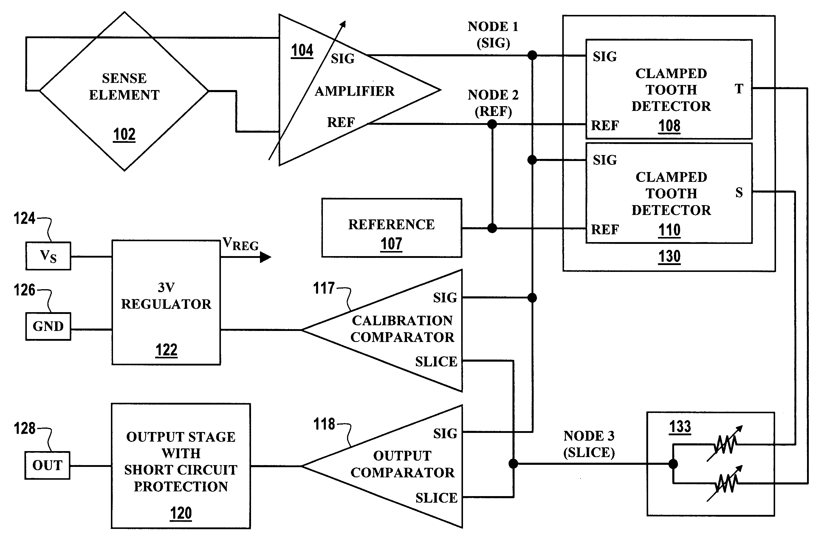
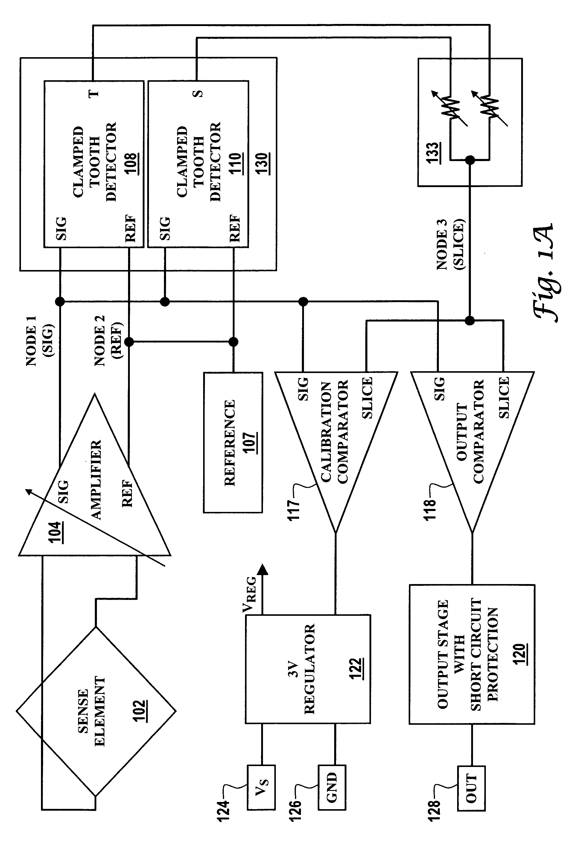
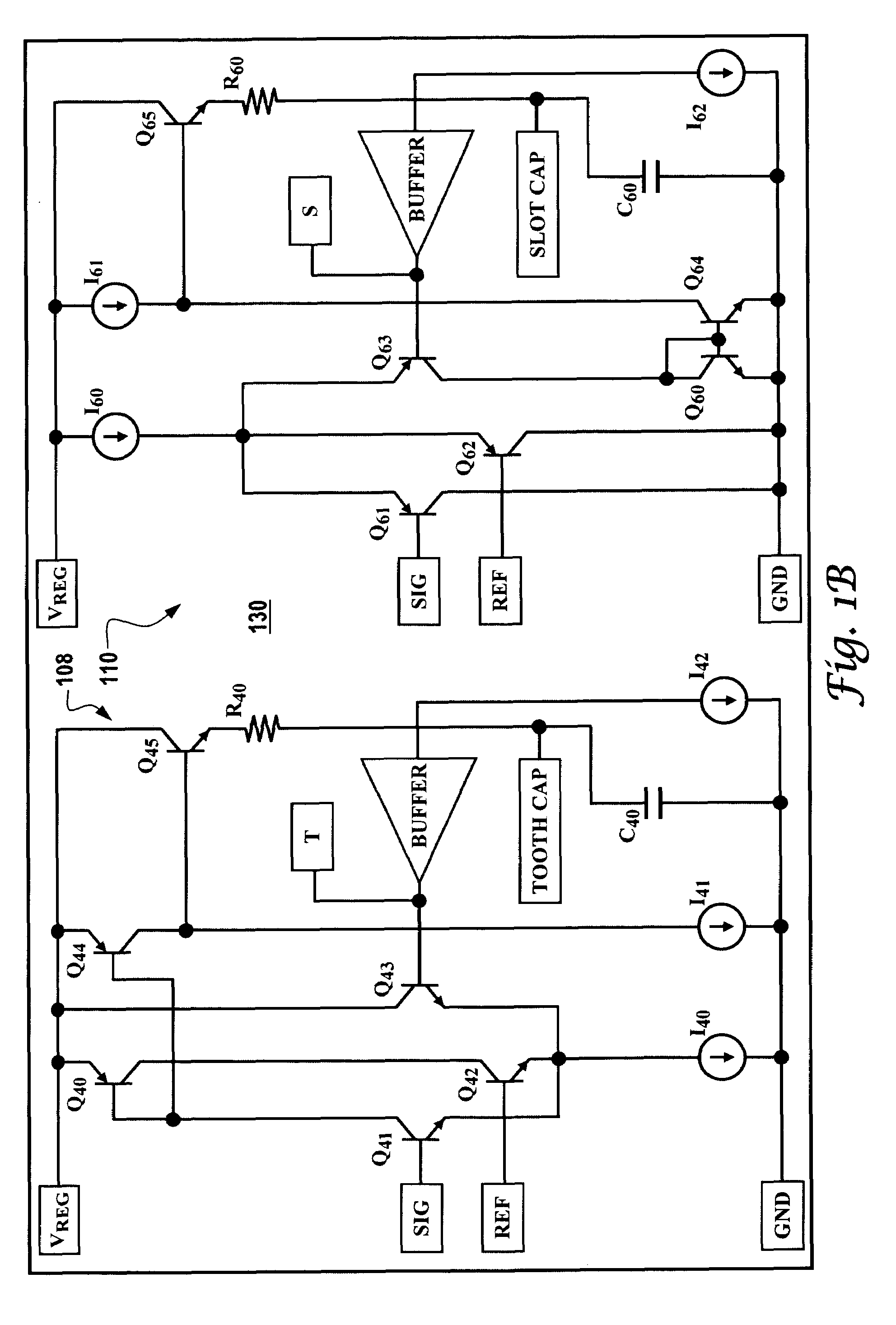
[0025]FIG. 1(a) illustrates a block diagram of a dual-detector system 100, which can be implemented in accordance with a preferred embodiment of the present invention. FIG. 1(b) illustrates a schematic diagram of a dual peak detector 130 that can be adapted for utilization with the dual-detector system depicted in FIG. 1(a) in accordance with a preferred embodiment. Note that in FIGS. 1(a) and 1(b), identical or similar parts are generally indicated by identical reference numerals.

[0026]System 100 generally includes a sensing element 102, which can be associated with and / or interact with a rotating target and biasing magnet, such as, for example, targets 220, 218 and / or 224 depicted in FIG. 2. The biasing magnet 508 possesses a magnet field such that the biasing magnet...


PUM


Abstract

Methods and systems for detecting a rotating target are disclosed herein, wherein a biasing magnet is associated with a rotating target in association with a dual peak detector. The rotating target generally comprises a plurality of teeth and at least one slot formed between at least one tooth of the rotating target. In general, the biasing magnet and the rotating target generate a magnetic signal having positive and negative peaks thereof. The dual peak detector includes a tooth detector and a slot detector, such that the dual peak detector detects a minimum and maximum peak of the magnetic signal generated by the biasing magnet and the rotating target. Additionally, a clamping circuit can be associated with the dual peak detector, wherein the clamping circuit can provide a true power on (TPO) functionality.

Description

TECHNICAL FIELD[0001]Embodiments are generally related to sensor devices, methods and systems. Embodiments are also related to cam and crankshaft sensors utilized in automotive applications. Embodiments are additionally related to Hall devices and True Power On (TPO) applications and capabilities.BACKGROUND OF THE INVENTION[0002]Various sensors are known in the magnetic-effect sensing arts. Examples of common magnetic-effect sensors include Hall effect and magnetoresistive technologies. Such magnetic sensors generally respond to a change in the magnetic field as influenced by the presence or absence of a ferromagnetic target object of a designed shape passing through the sensory field of the magnetic-effect sensor. The sensor can then provide an electrical output, which can be further modified as necessary by subsequent electronics to yield sensing and control information. The subsequent electronics may be located either onboard or outboard of the sensor package.[0003]Many of the se...

Claims


Application Information

Patent Timeline
Patent Type & Authority Patents(United States)
IPC IPC(8): G01B7/30G01D5/14G01D5/244
CPCG01D5/145G01D5/147G01D5/24452G01D5/2448G01D5/2449G01D18/001
Inventor MURDOCK, JOSEPH K.FURLONG, GREG R.HANCOCK, PETER G.HINTZ, FRED W.
Owner HONEYWELL INT INC
Why Eureka
Try Eureka