Alternative video sync detector

Inactive Publication Date: 2005-12-20
INTERSIL INC
View PDF15 Cites 10 Cited by
  • Summary
  • Abstract
  • Description
  • Claims
  • Application Information

AI Technical Summary

Benefits of technology

[0015]In another embodiment in accordance with the present invention, circuitry is configured to reduce amplifier DC offset which can cause errors in a perceived VSLICE level. The circuitry includes a first amplifier which receives the composite video signal and is connectable by switches in one of three positions TCOMP, TTIP and TH. In the TCOMP position the first amplifier acts as a comparator with no feedback to compare the value VSLICE+VTIP with the composite video signal. VSLICE is set between VTIP and VREF based on values stored on capacitors in the circuit. The TCOMP position is used prior to the negative going synchronization tip edge of the composite video signal. After the negative going edge of the synchronization tip, the

Problems solved by technology

Unfortunately, the sync tip almost never has a known DC level.
In fact, most composite signals are AC coupled and the average DC level varies unpredictably wi

Method used


Image

  • Alternative video sync detector
  • Alternative video sync detector
  • Alternative video sync detector

Examples


Embodiment Construction

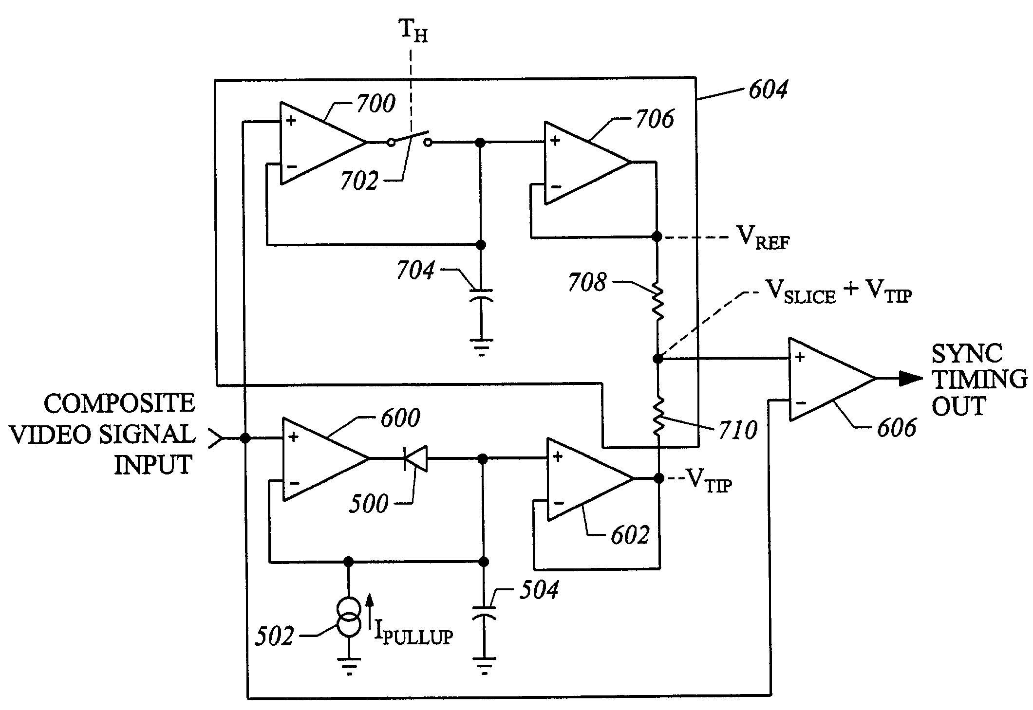
[0025]The present invention provides a circuit for establishing a sync tip baseline without clamping the most negative portion of the composite signal to a known value. Instead of clamping the sync tip, the negative peak detector follows variations in the composite signal. The circuit of the present invention includes a negative peak detector as shown in FIG. 5.

[0026]As shown in FIG. 5, the negative peak detector is a rectifier including a p-n type bipolar diode 500, or other rectifying element, with the composite video signal provided to the n terminal and the sync tip level output provided at the p terminal. The negative peak detector also includes a weak current source 502 and a capacitor 504 connecting the p terminal of diode 500 to ground. The current source 502 functions to charge the capacitor 504. The output of the negative peak detector is a reference voltage which tracks the sync tip voltage level VTIP.

[0027]FIG. 6 shows the negative peak detector of FIG. 5 with buffering ...


PUM


Abstract

A circuit for generating video synchronization timing signals includes a negative peak detector (FIG. 5) for following variations of a composite video signal (FIG. 1), rather than clamping the most negative voltage of the composite video signal. The negative peak detector provides a voltage level VTIP representative of the voltage at the synchronization tip of the composite video signal. A sample and hold circuit (700, 702, 704) is used to add an offset VSLICE to VTIP, VSLICE being a voltage level of the breezeway, color burst, or back porch segments of the composite video signal, or a combination of these segments. The sample and hold circuit generates a signal VREF, and is connected by a resistor divider (708,710) to the negative peak detector to form the signal VTIP+VSLICE provided to an amplifier (606) functioning as a comparator. The signal VSLICE+VTIP is compared in comparator (606) with the composite video signal to provide an overall circuit output. Buffering is provided at the input of the negative peak detector by amplifier (600) to reduce any DC offset from the diode of the negative peak detector. To prevent amplifier DC offset error voltages from affecting the perceived VSLICE level, an amplifier (800) can be connected in a first position TTIP as part of a negative peak detector to store VTIP on a capacitor, in a second position TH as part of a sample and hold circuit to store VREF on a capacitor, and in a third position TCOMP to compare VSLICE+VTIP measured from the capacitors with the composite video signal to generate the overall circuit output.

Description

PRIORITY CLAIM[0001]This application is a continuation of and claims priority to U.S. patent application No. 09 / 398,375, filed Sep. 17, 1999 (now U.S. Pat. No. 6,573,943).BACKGROUND OF THE INVENTION[0002]1. Field of the Invention[0003]This invention relates to the field of video circuits. More particularly, this invention relates to a circuit for detecting synchronizing pulses embedded in composite waveforms of a video signal.[0004]2. Description of the Related Art[0005]FIG. 1 illustrates components of a composite video waveform. The composite waveform contains: a horizontal sync pulse or sync tip used for receiver scan timing; a “breezeway” where the level is a reference for video intensity; a color burst which is a series of sinewaves at a very precise frequency and phase, used as a color reference; a back porch which is a level reference similar to the breezeway occurring after the colorburst segment; and the picture occurring after the back porch, the picture being any possible ...

Claims


Application Information

Patent Timeline
IPC IPC(8): H04N5/08
CPCH04N5/08
Inventor HARVEY, BARRY
Owner INTERSIL INC
Why Eureka
Try Eureka