Tilt-compensated interferometers

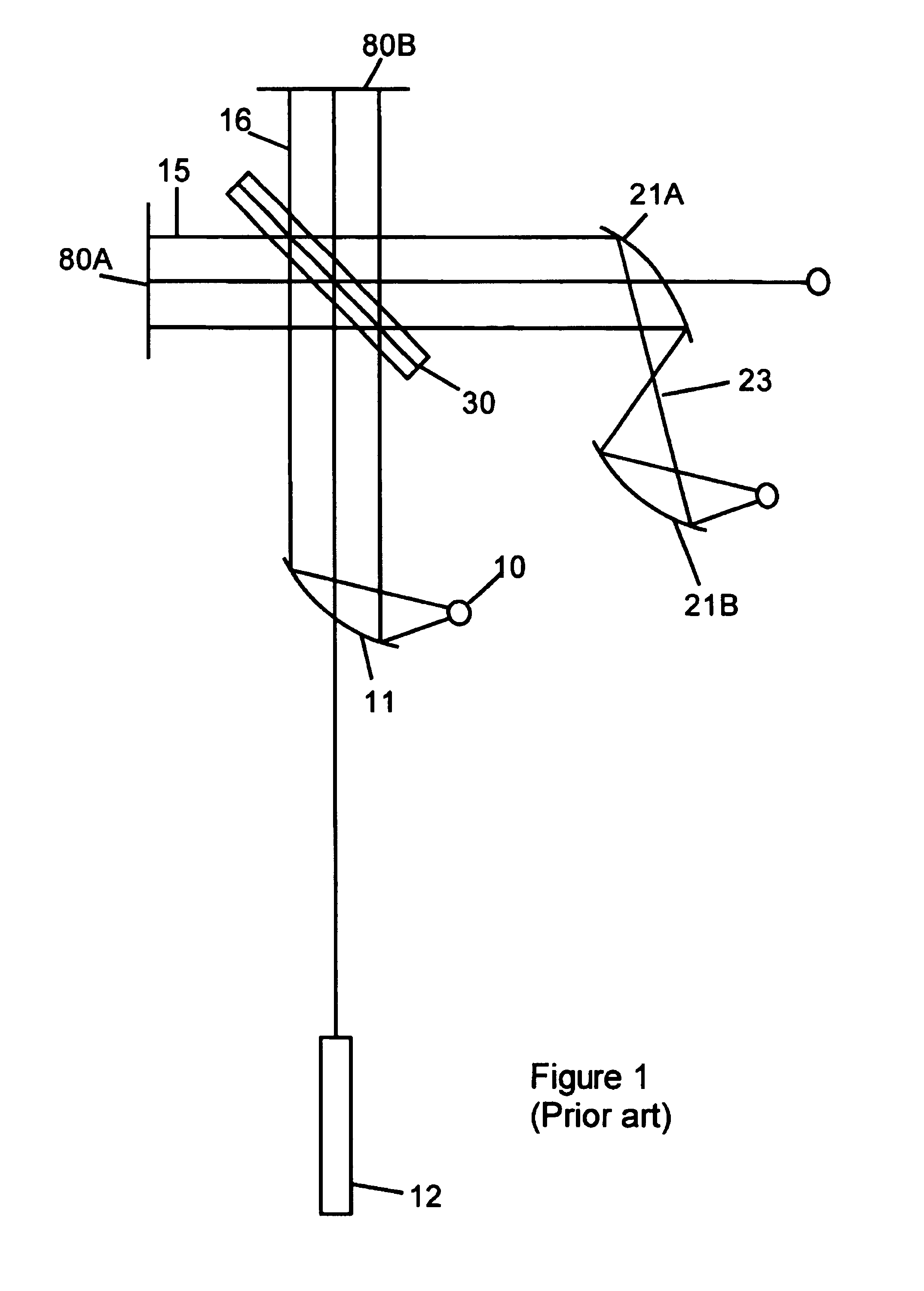
a technology of tilt compensation and interferometer, which is applied in the field of new interferometers, can solve the problems of long optical paths required for optical tilt compensation, beams of radiation not reaching exactly the intended detection location, and two end mirrors b>80/b>a and b>80/b>b are susceptible to misalignment with each other, so as to improve photometric accuracy, improve throughput, and compact design

Inactive Publication Date: 2005-11-22
MANNING CHRISTOPHER J
View PDF3 Cites 15 Cited by
  • Summary
  • Abstract
  • Description
  • Claims
  • Application Information

AI Technical Summary

Benefits of technology

[0011]The present invention described herein substantially increases throughput relative to prior art tilt-compensated interferometers, while enabling very compact designs. Tilt compensation can improve photometric accuracy and also improve very rapid scan operation of a reciprocating mirror interferometer. The present invention provides a related series of novel tilt-compensated interferometer designs comprised of a beamsplitter rigidly mounted to a roof reflector, combined with various other optical components. By “roof reflector”, what is meant is a pair of abutted mirror facets that are perpendicular to interferometric tolerances, as is known in various optical arts. The present invention is illustrated with several embodiments in which the advantages are employed to achieve a series of related ends. Interferometric alignment means an accuracy on the order of the wavelength of the radiation being used in the interferometer. In the context of angles, interferometric alignment means that the displacement of a beam by angular deviation is on the order or less than a wavelength of electromagnetic radiation over the length of travel. Angles this small are generally about 1 arcsecond or a few microradians.

Problems solved by technology

A disadvantage of the Michelson interferometer and many related designs is that the two end mirrors 80A and 80B are susceptible to misalignment with each other and with the beamsplitter 30.
Slight residual misalignment may result in a beam of radiation not reaching exactly the intended detection location.
However, a disadvantage of the prior art is the long optical paths required for optical tilt compensation.
For example, the approaches of Frosch, Woodruff, Solomon, Turner, and others, impose an undesirable limit on throughput, which is the product of solid angle and aperture area.
This is not presently the preferred approach to construction, because the resulting assemblies are more fragile and thought to be more expensive than the construction of the preferred embodiments described below.

Method used


Image

  • Tilt-compensated interferometers
  • Tilt-compensated interferometers
  • Tilt-compensated interferometers

Examples


Embodiment Construction

[0027]The operation of the various interferometer embodiments of the invention described below is analogous to the operation of the prior art Michelson interferometer. The same external components such as source, laser, detector and laser detector may be used with the designs described below to achieve ends that are either known or as-yet undiscovered. Electronics and computers are preferably used to process the data according to known means. Many of the known methods of operation are detailed in Griffiths and deHaseths' book, cited above.

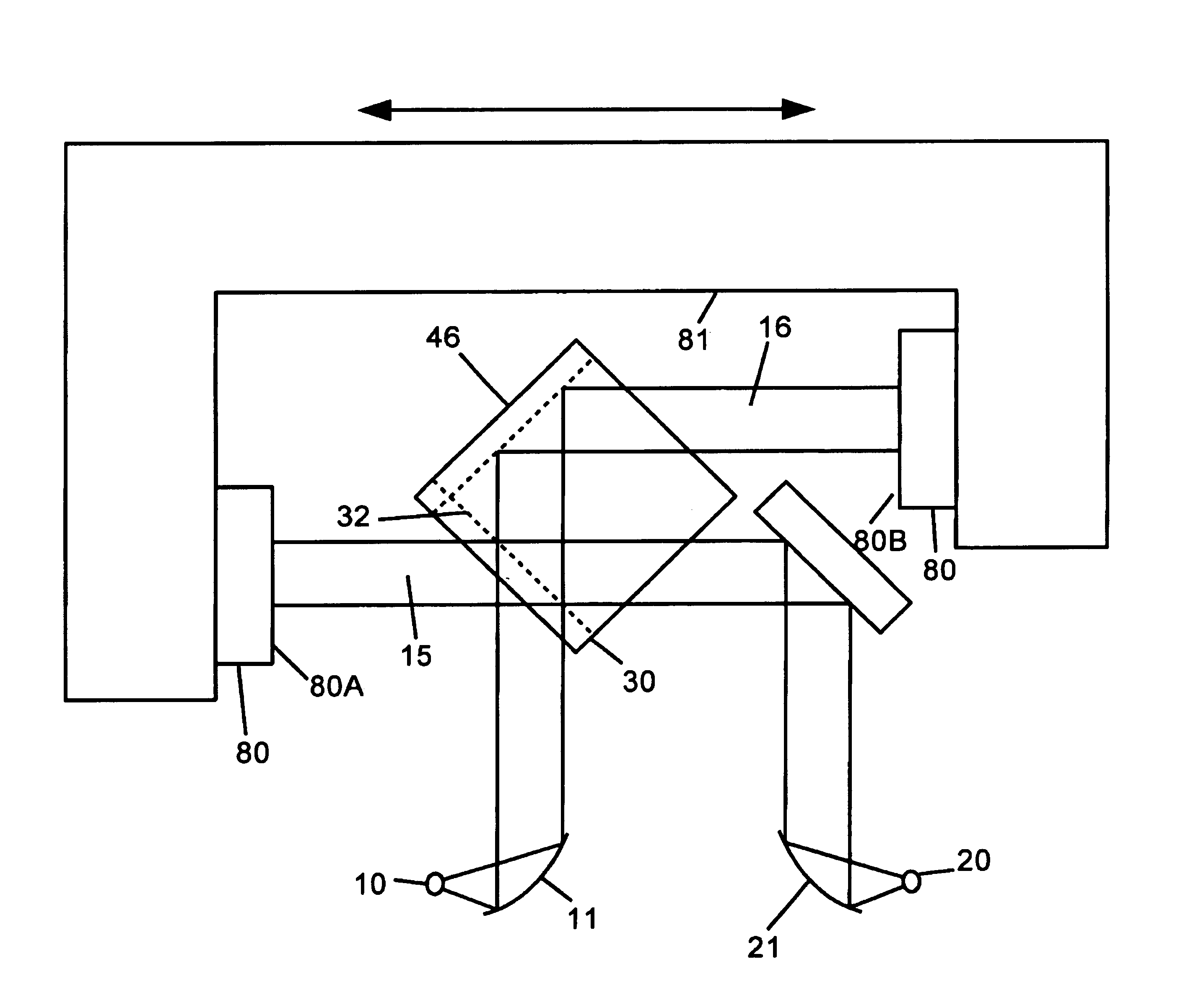
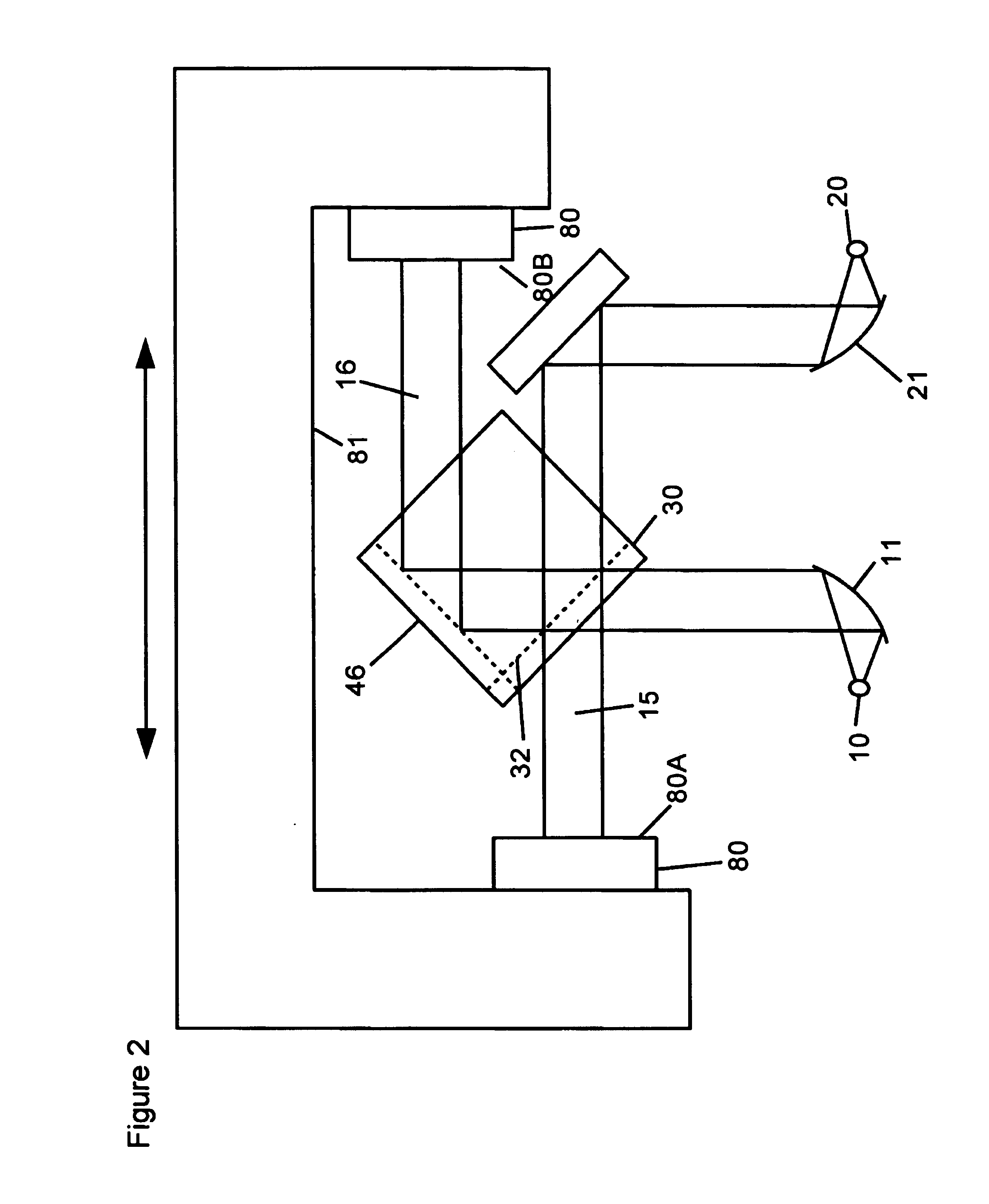
[0028]FIG. 2 shows a plan view of a permanently aligned interferometer for which errors of the motion of the scanning assembly 81 are compensated. The assembly 81 may be supported by a variety of mechanisms including ball bearing slides, roller bearings, flex pivots, or airbearings to provide smooth, essentially rectilinear motion. The beamsplitter is indicated by 30 and roof reflector / beamsplitter mounting monolith is indicated by 46. Two mirrors ...


PUM


Abstract

The tilt-compensated interferometers of the present invention are novel variations of Michelson's interferometer that use tilt- and shear-compensation to provide excellent photometric accuracy even when there are imperfections in the scanning motion used to produce variation of path difference. The tilt-compensation mechanism of the present invention consists of antiparallel reflections from a beamsplitter element and a roof reflector element, which elements are held rigidly in alignment. Several particularly useful embodiments of the invention are described. Other advantages of the present invention include photometric stability and reduced cost because manual alignment is not required. This interferometer has applications in spectrometry, spectral imaging and metrology.

Description

CROSS REFERENCE TO RELATED APPLICATIONS[0001]This is a CONTINUATION of prior application Ser. No. 09 / 299,022, filed on Apr. 26, 1999, entitled TILT-COMPENSATED INTERFEROMETERS, which will issue as on Oct. 22, 2002 as U.S. Pat. No. 6,469,790. The application Ser. No. 09 / 299,022 claimed priority under 35 U.S.C. § 119(e) from Provisional Patent Application No. 60 / 120,736, filed Feb. 18, 1999. The application Ser. No. 09 / 299,022 was a continuation of application Ser. No. 08 / 959,030, filed Oct. 28, 1997, which issued as U.S. Pat. No. 5,898,495. The application Ser. No. 09 / 299,022 and 60 / 120,736 and 08 / 959,030 applications and U.S. Pat. Nos. 5,898,495 and 6,469,790 are hereby incorporated herein by reference for the entirety of their disclosures.BACKGROUND OF THE INVENTION[0002]1. Field of the Invention[0003]It is an object of the present invention to provide new interferometers, which are better than prior art in respect to stability, scan speed and cost of manufacture. It is an object o...

Claims


Application Information

Patent Timeline
Patent Type & Authority Patents(United States)
IPC IPC(8): G01J3/453G01J9/02
CPCG01J3/453G01J3/4532G01J3/4535G01J9/0215G01B9/02061
Inventor MANNING, CHRISTOPHER J.
Owner MANNING CHRISTOPHER J
Why Eureka
Try Eureka