Engine integrated auxiliary power unit

a technology of auxiliary power unit and engine, which is applied in the direction of efficient propulsion technology, machines/engines, transportation and packaging, etc., can solve the problem that no one has developed a truly engine integrated auxiliary power unit, and achieve the effect of reducing parasitic losses, reducing weight and cost, and eliminating heavy bleed air ducting

Inactive Publication Date: 2005-11-29
RAYTHEON TECH CORP
View PDF14 Cites 24 Cited by
  • Summary
  • Abstract
  • Description
  • Claims
  • Application Information

AI Technical Summary

Benefits of technology

[0008]It is yet another object of the present invention to provide an engine integrated auxiliary power unit which provides weight and cost savings.
[0009]It is still another object of the present invention to provide an engine integrated auxiliary power unit which eliminates heavy bleed air ducting, reduces parasitic losses, and simplifies transmission systems.

Problems solved by technology

To date, however, no one has developed a truly engine integrated auxiliary power unit.

Method used


Image

  • Engine integrated auxiliary power unit
  • Engine integrated auxiliary power unit
  • Engine integrated auxiliary power unit

Examples


Embodiment Construction

)

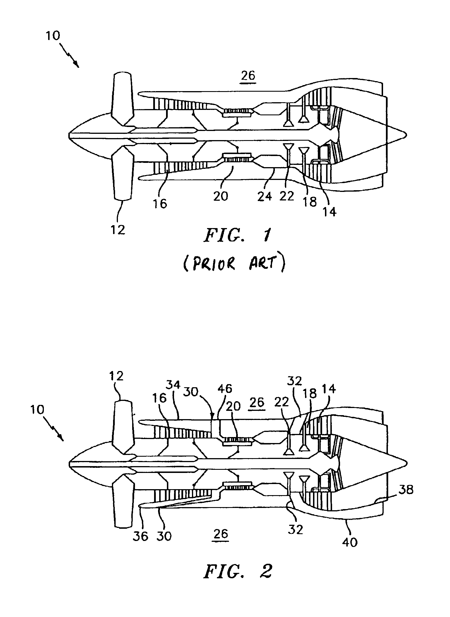
[0016]The present invention involves the integration of an auxiliary power unit into an engine cycle, thus eliminating the need for a conventional auxiliary power unit. In principle, the high pressure system of a two- or three-spool engine can be operated independently from the rest of the engine—given that compressors and turbines are aerodynamically de-coupled.

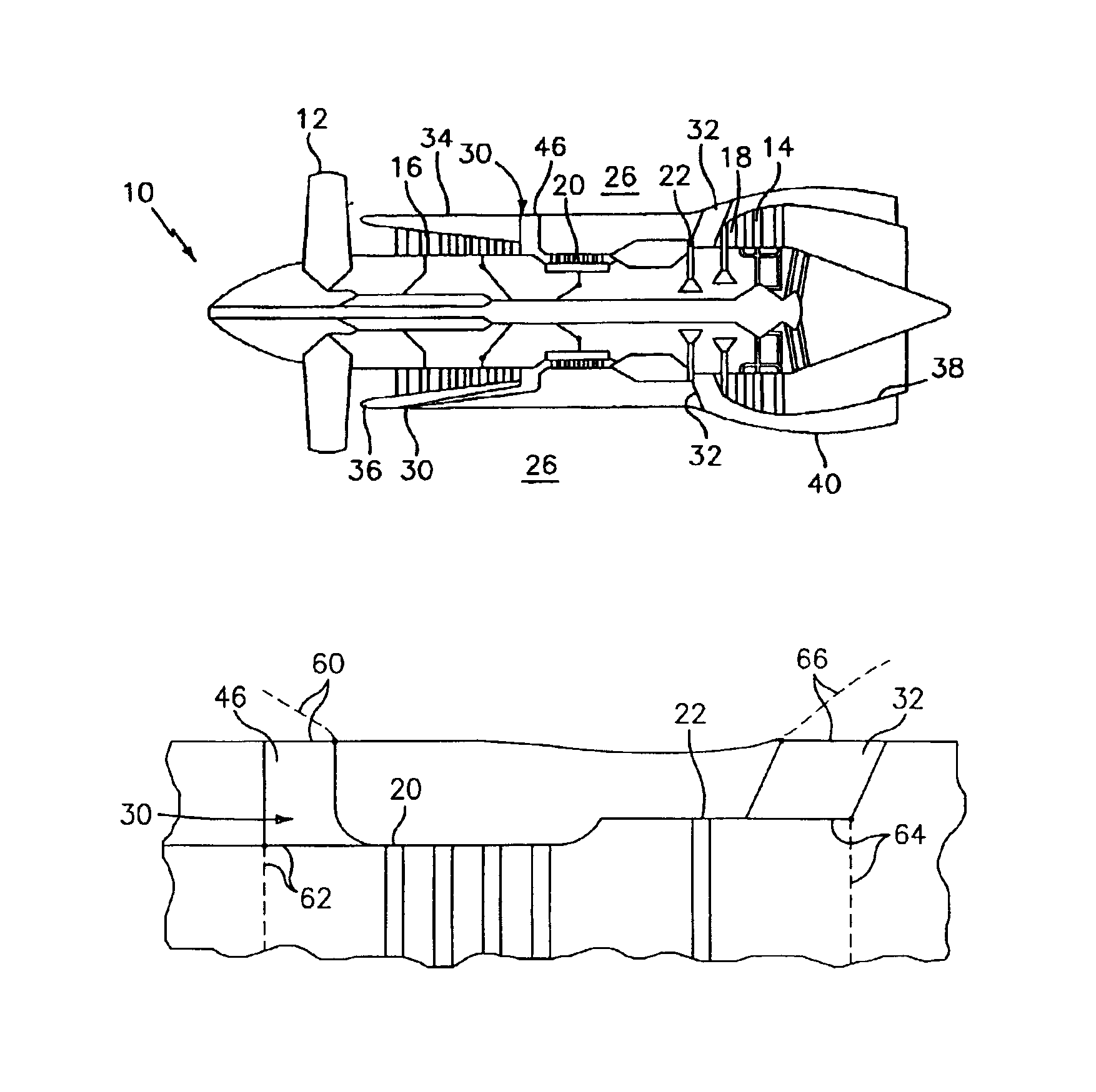
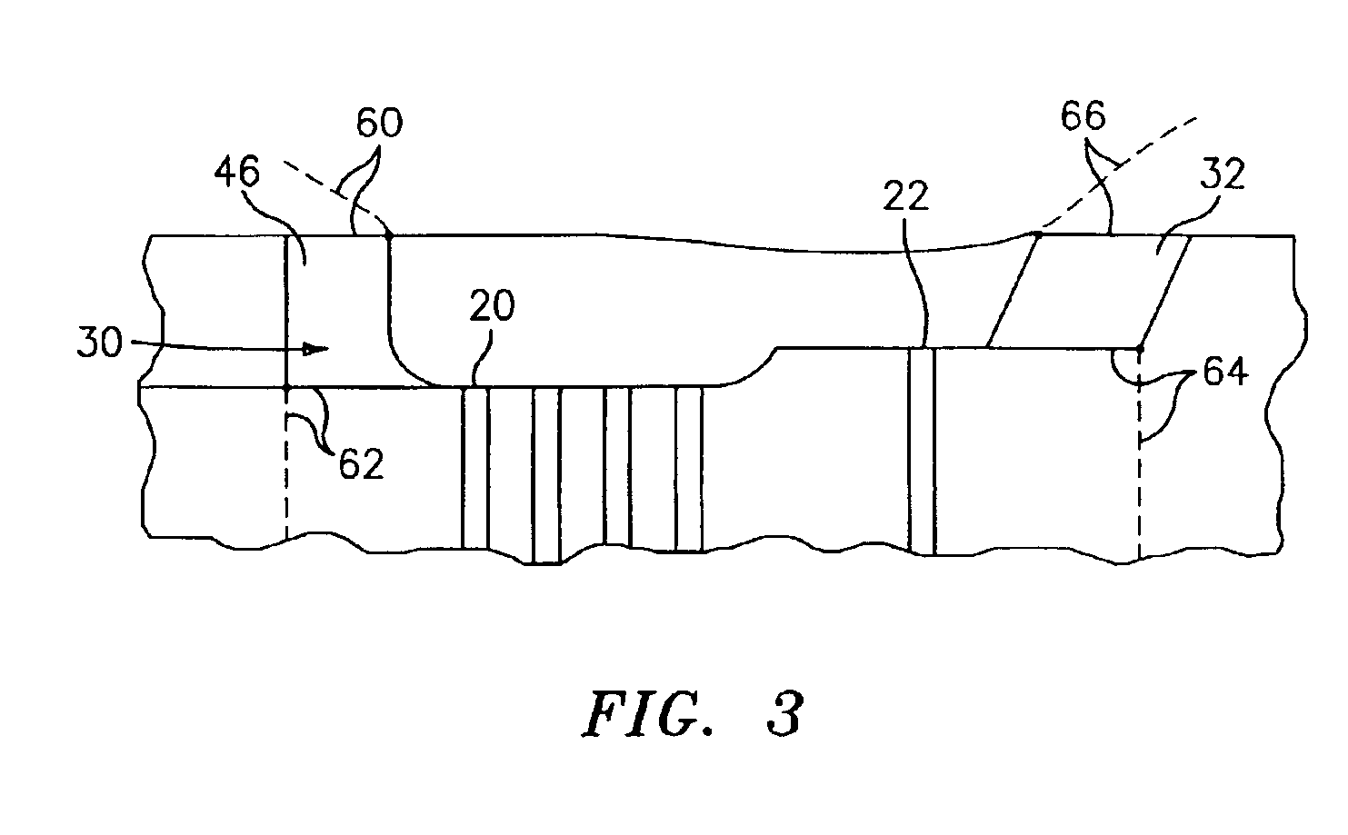
[0017]Referring now to FIG. 2 of the drawings, a three-spool engine is illustrated. Integration of the auxiliary power unit into the engine cycle is achieved by providing one or more variable inlet ports 30 for allowing air to be introduced directly into an inlet of a high pressure compressor 20. The air introduced through the port(s) 30 is used to drive the high pressure compressor 20 and the high pressure turbine 22. Air which has been passed through the high pressure turbine 22 is ducted out of the engine via one or more exit ports 32. By flowing air through the high pressure compressor 20 and the high pressure turbine 2...


PUM


Abstract

The present invention relates to an engine integrated auxiliary power unit. The engine comprises a high pressure spool which includes a high pressure compressor connected to a high pressure turbine and a low pressure spool which includes a low pressure compressor connected to a low pressure turbine. The engine further has a system for independently operating the high pressure spool and thus allowing the high pressure spool to function as an auxiliary power unit.

Description

CROSS REFERENCE TO RELATED APPLICATION(S)[0001]The present application claims the benefit of U.S. Provisional Patent Application Ser. No. 60 / 348,889, filed Jan. 16, 2002, to Glahn et al. entitled ENGINE INTEGRATED AUXILIARY POWER UNIT.BACKGROUND OF THE INVENTION[0002]The present invention relates to an engine integrated auxiliary power unit for use on an aircraft.[0003]FIG. 1 shows a schematic of a modern, high-bypass, three-spool turbofan engine 10. Air enters the engine 10 through an inlet diffuser (not shown) and reaches the fan 12, which acts as a low pressure compressor and which is driven by a three-stage low turbine 14. Downstream of the fan 12, a part of the air is compressed fully and passed through the intermediate pressure compressor 16, which is driven by the intermediate turbine 18, and then through the high pressure compressor 20, which is driven by the high pressure turbine 22, into the combustion chamber 24. The remainder of the airflow bypasses the combustion chambe...

Claims


Application Information

Patent Timeline
Patent Type & Authority Patents(United States)
IPC IPC(8): B64D33/02B64D33/04B64D41/00F02C3/13F02C7/32F02C7/36F02K3/06F02K3/075F02K3/077
CPCB64D33/02B64D33/04B64D41/00F02C3/13F02C7/32F02K3/075F02K3/077Y02T50/44Y02T50/671Y02T50/40Y02T50/60
Inventor GLAHN, J. AXELSAHM, MICHAEL K.
Owner RAYTHEON TECH CORP
Why Eureka
Try Eureka