
Face seal assembly

Inactive Publication Date: 2005-11-29
EATON INTELLIGENT POWER LIMITED
View PDF24 Cites 12 Cited by
  • Summary
  • Abstract
  • Description
  • Claims
  • Application Information

AI Technical Summary

Benefits of technology

[0011]It is a further object of this invention to provide a face seal assembly which is simple and easy to install.
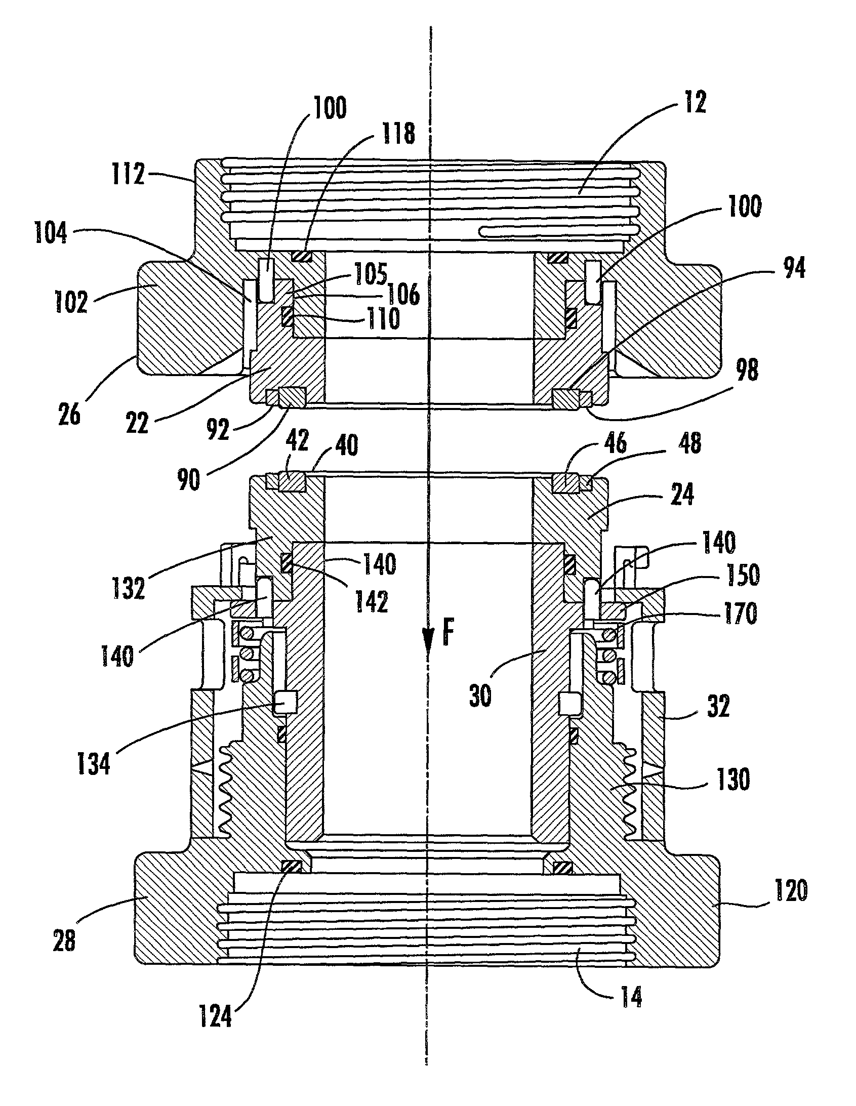
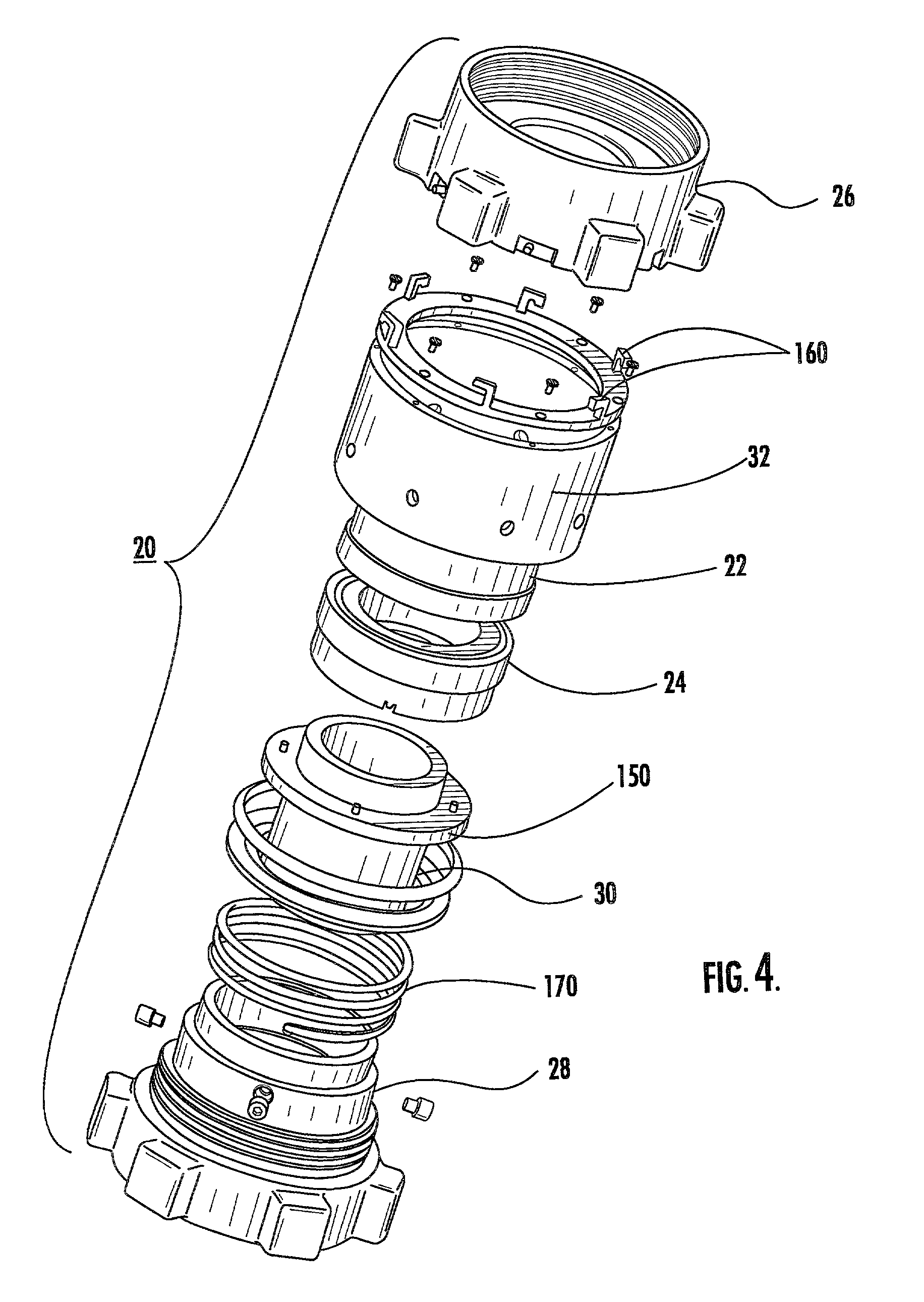
[0030]A method of making a face seal assembly in accordance with this invention features forming an annular mating ring housing to have a proximal end surface with a channel therein, disposing a mating ring insert in the channel, the mating ring insert including a mating ring compressed within a first band to maintain the integrity of the mating ring, forming an annular sealing ring housing to have a distal end surface with a channel therein, and disposing a sealing ring insert in the channel, the sealing ring insert including a sealing ring compressed within a second band to maintain the integrity of the sealing ring. The mating ring is oriented to face the sealing ring to prevent fluid from escaping therebetween.

Problems solved by technology

This packing material generates excessive heat and when the packing fails, it can take between one to five hours to replace the packing resulting in costly down time for the drilling operations.
Moreover, the top drive unit itself is located about 20 feet up off the drilling platform and workmen must use sledgehammers to replace the packing resulting in a frustrating and hazardous procedure.
And, when the packing fails, it fails catastrophically resulting in many barrels of expensive mud being spilled at a cost of a thousand dollars per barrel.
Also, the spilled mud must be reclaimed at a significant cost.
Worse yet, the packing type seal is inconsistent and sometimes only lasts 5 hours and other times lasts 500 hours.
Thus, the prior art packing seal has plagued the drilling industry with inconsistent seal life, high torque and heat generation, and catastrophic leakage when the seal fails.
Mechanical face seals, known in other industries, have not been used in the drilling industry due to the extreme operating conditions and caustic environment.
Also, face seals are usually constructed from brittle ceramic material which, when subjected to high intemal pressures, would crack and fail.
Indeed, those skilled in the art of mechanical face seals have studied the drilling industry top drive unit and concluded that conventional mechanical face seals could not be used.

Method used


Image

  • Face seal assembly
  • Face seal assembly
  • Face seal assembly

Examples


Embodiment Construction

[0053]Aside from the preferred embodiment or embodiments disclosed below, this invention is capable of other embodiments and of being practiced or being carried out in various ways. Thus, it is to be understood that the invention is not limited in its application to the details of construction and the arrangements of components set forth in the following description or illustrated in the drawings.

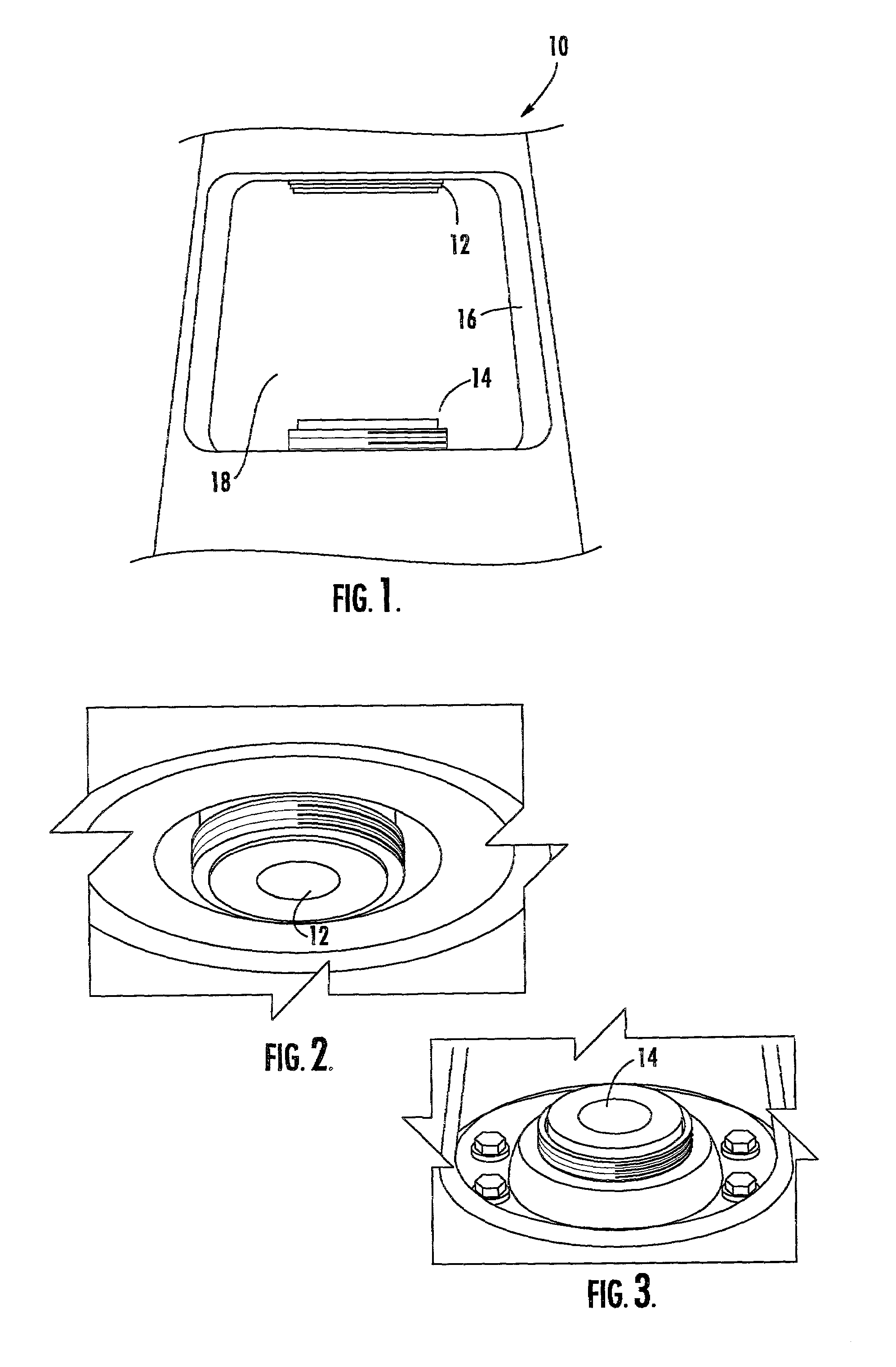
[0054]FIG. 1 shows top drive unit 10 of a particular drilling system which includes upper stationary drive pipe 12 and lower rotating drive pipe 14 within housing 16. FIGS. 2 and 3 also show upper pipe 12 and lower pipe 14, respectively. Access to both pipes is via an 11.19 inch window 18 in top drive unit 10.

[0055]As discussed in the background section above, caustic mud at pressures in excess of 5000 psi travels through both pipes and, in the prior art, the junction between the pipes is sealed by V-type packing. This packing material, however, generates excessive heat and when it fails it...


PUM


Abstract

A face seal assembly including an annular mating ring housing having a proximal end surface with a channel therein, a mating ring insert disposed in the channel, the mating ring insert including a mating ring compressed within a first band to maintain the integrity of the mating ring. An annular sealing ring housing has a distal end surface with a channel therein, and a sealing ring insert is disposed in the channel, the sealing ring insert including a sealing ring compressed within a second band to maintain the integrity of the sealing ring. The mating ring faces the sealing ring to prevent fluid from escaping therebetween. A method of making such a face seal assembly is also disclosed as is a complete face seal assembly useful in the top drive unit of an offshore drilling unit.

Description

FIELD OF THE INVENTION[0001]This invention relates to a new face seal useful in, inter alia, applications where the inner diameter of the face seal is subject to high pressures. This invention also relates to a complete face seal assembly useful, inter alia, in connection with the top drive drilling unit of an offshore or land based drilling rig.BACKGROUND OF THE INVENTION[0002]The top drive drilling unit of an offshore drilling rig includes a stationary pipe and a rotating pipe disposed in a housing. A caustic and abrasive fluid called mud in the industry flows from the stationary pipe to the rotating pipe at pressures in excess of 5,000 psi. The mud is used to break up rocks and sediment on the ocean floor.[0003]To seal the stationary pipe with respect to the rotating pipe, “V-type” rubber packing material is used. This packing material generates excessive heat and when the packing fails, it can take between one to five hours to replace the packing resulting in costly down time fo...

Claims


Application Information

Patent Timeline
IPC IPC(8): E21B3/02F16J15/34
CPCF16J15/3464E21B3/02E21B3/022
Inventor BERARD, GERALD M.
Owner EATON INTELLIGENT POWER LIMITED
Learn More