Apparatus and method for machining in confined spaces

a technology for machining apparatus and confined space, which is applied in the direction of manufacturing tools, electrolysis components, and vibration holders of electrolysis devices, etc., can solve the problems of inability to use in confined spaces, large ecdm and edm tools, and electric discharg

Active Publication Date: 2005-11-29
GENERAL ELECTRIC CO
View PDF12 Cites 21 Cited by
  • Summary
  • Abstract
  • Description
  • Claims
  • Application Information

AI Technical Summary

Problems solved by technology

In ECDM, bubbles resulting from electrolytic dissolution cause a non-conducting region between the electrode and material, subsequently leading to an electrical discharge owing to a high electrical voltage applied to this non-conducting region.
Unfortunately, currently available ECDM and EDM tools are large, cumbersome, and have an inability to be used in confined spaces.
Additionally, ECDM and EDM currently only drill holes around 6 mm in diameter, when a larger diameter drill hole may be needed to efficiently drill out certain hardware such as pins and screws.
As stated above, currently available EDM and ECDM tools are impossible or very difficult to use in confined spaces.
Once these pins have seized, they are very difficult and time consuming to remove by using such known means as hammering or mechanical drilling.
Part of the difficulty in removing these pins and tabs is that space is very limited between the hubs of a turbomachine rotor, thus making it very awkward if not impossible to drill out the pins and tabs.
Additionally, the blades extend around a 360 degree interior of the turbo machine casing, making it difficult to position cumbersome tools to drill out all the pins.

Method used


Image

  • Apparatus and method for machining in confined spaces
  • Apparatus and method for machining in confined spaces
  • Apparatus and method for machining in confined spaces

Examples


Embodiment Construction

[0018]A detailed description of several embodiments of the disclosed apparatus and method are presented herein by way of exemplification and not limitation with reference to FIGS. 1 through 4.

DISCHARGE MACHINING

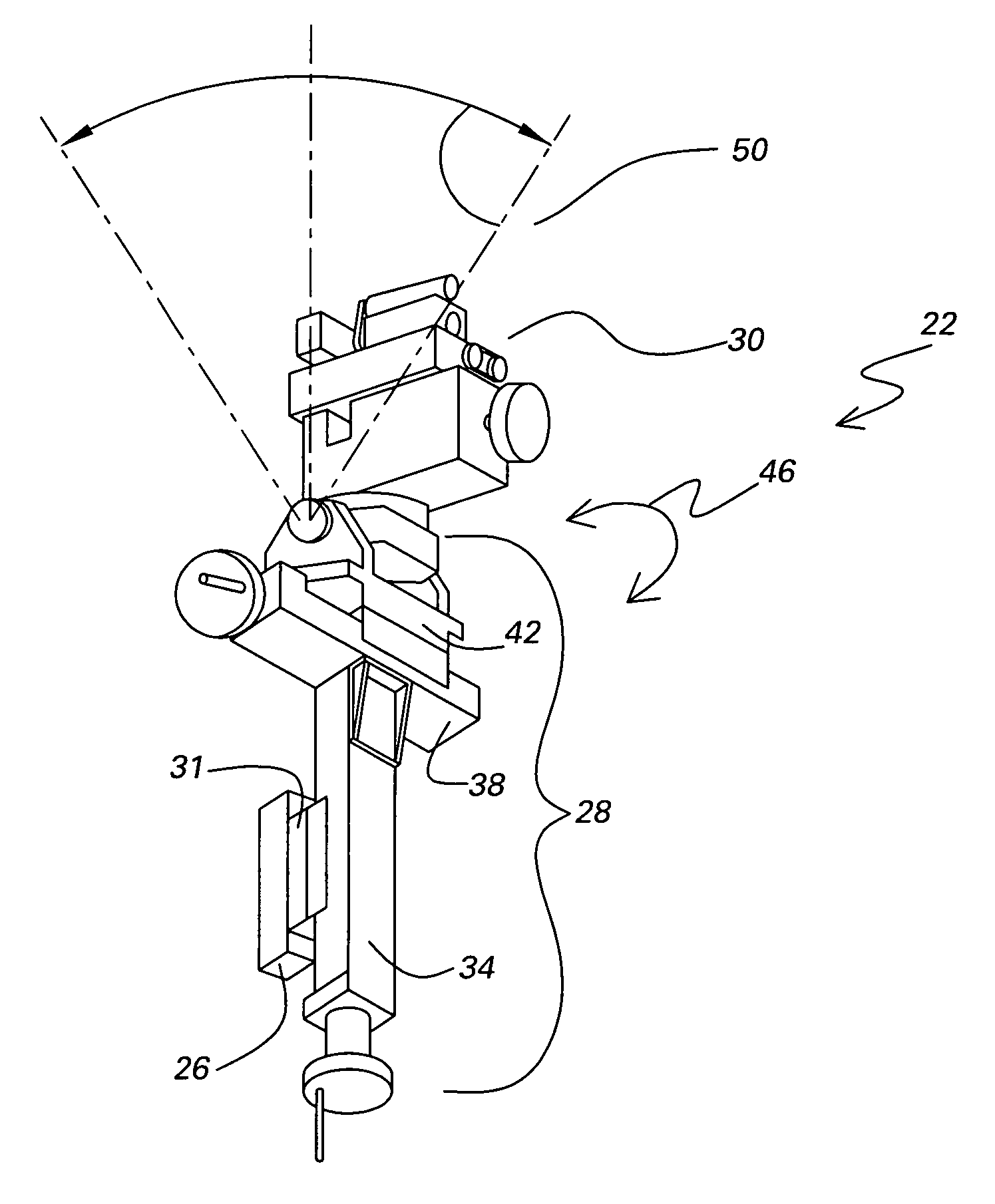
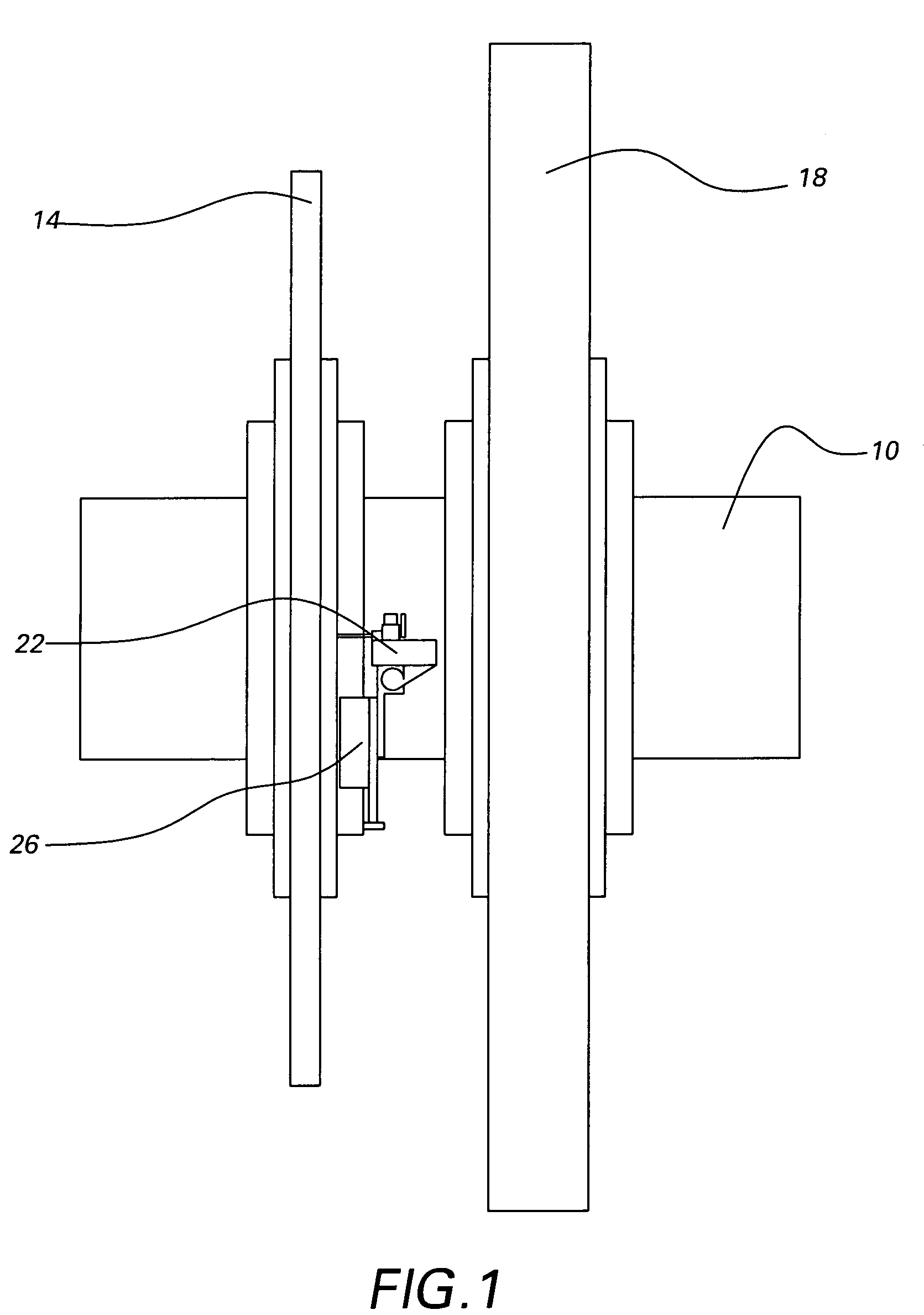
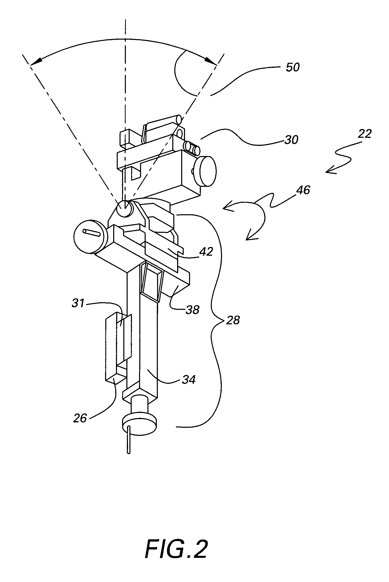
[0019]FIG. 1 shows a non-limiting example of a confined space where a portable and small ECDM or EDM apparatus would be useful. A side view of part of a rotor 10 from a turbomachine is shown. In this example the rotor 10 is a steam turbine rotor with a L-1 stage hub 14 and a L-0 stage hub 18. Although FIG. 1 shows the space between two hubs of a rotor, this is only one of many possible uses of such an apparatus in confined spaces. Attached to the L-1 stage hub 14 is a disclosed apparatus 22. The disclosed apparatus 22 is attached to the hub 14 via an electromagnet 26. The electromagnet 26 allows the apparatus 22 to be positioned in a variety of orientations with respect to a work piece, in contrast to commercially available ECDM and EDM tools, which are oriented to vertically...


PUM

PropertyMeasurementUnit
diameteraaaaaaaaaa
diameteraaaaaaaaaa
heightaaaaaaaaaa

Abstract

A machining apparatus is provided. The machining apparatus includes a discharge machining head assembly and a slide assembly supporting the head assembly. The machining apparatus also includes an electromagnet configured to support the slide assembly in a position on a work piece to machine an area. The slide assembly permits linear displacement of the head assembly generally parallel to the supporting work piece surface.

Description

TECHNICAL FIELD[0001]The disclosed apparatus relates to a machining apparatus and method for use in a confined space. More specifically, the disclosed apparatus relates to a machining apparatus that uses either an electrochemical discharge machining technique or an electro-discharge machining technique.BACKGROUND OF THE INVENTION[0002]Electrochemical machining (ECM) and Electro-discharge machining (EDM) are two techniques used in industry for the machining of metals. In EDM, a DC voltage is applied to a drill electrode and the work piece is eroded by a spark formation in a gap between the drill electrode and the work piece. A dielectric liquid is usually forced into the gap between the electrode and the work piece.[0003]In ECM, a drill electrode is placed in proximity to the work piece and an electric potential is placed across the drill electrode and the work piece. Electrolyte is forced into the gap between the electrode and the work piece, and work material is removed by electro-...

Claims


Application Information

Patent Timeline
Patent Type & Authority Patents(United States)
IPC IPC(8): B23H7/26B23H9/00B23H9/10B23H9/14B23H11/00
CPCB23H7/26B23H7/265B23H9/00B23H9/14
Inventor LEE, MARTIN KIN-FEISASSATELLI, JOHN MATTHEWFISCHER, TODD JOSEPHROBERTS, DENNIS WILLIAM
Owner GENERAL ELECTRIC CO
Why Eureka
Try Eureka