Method of controlling the charging of a battery

a battery and charging method technology, applied in the field of electronic devices, can solve the problems of slow recharging, three hours of computing time, and requiring about three times as long to be recharged,

Inactive Publication Date: 2005-11-29
MAXIM INTEGRATED PROD INC
View PDF217 Cites 54 Cited by
  • Summary
  • Abstract
  • Description
  • Claims
  • Application Information

AI Technical Summary

Problems solved by technology

Such batteries provide roughly three hours of computing time, but require about three times as long to be recharged.
Such slow recharging is a problem and typically demands that users have several batteries with some recharging while others are being used.
However, known battery chargers cannot automatically adapt to such a variety charging conditions and remain simple to use.

Method used


Image

  • Method of controlling the charging of a battery
  • Method of controlling the charging of a battery
  • Method of controlling the charging of a battery

Examples


Embodiment Construction

[0020]Functional Overview

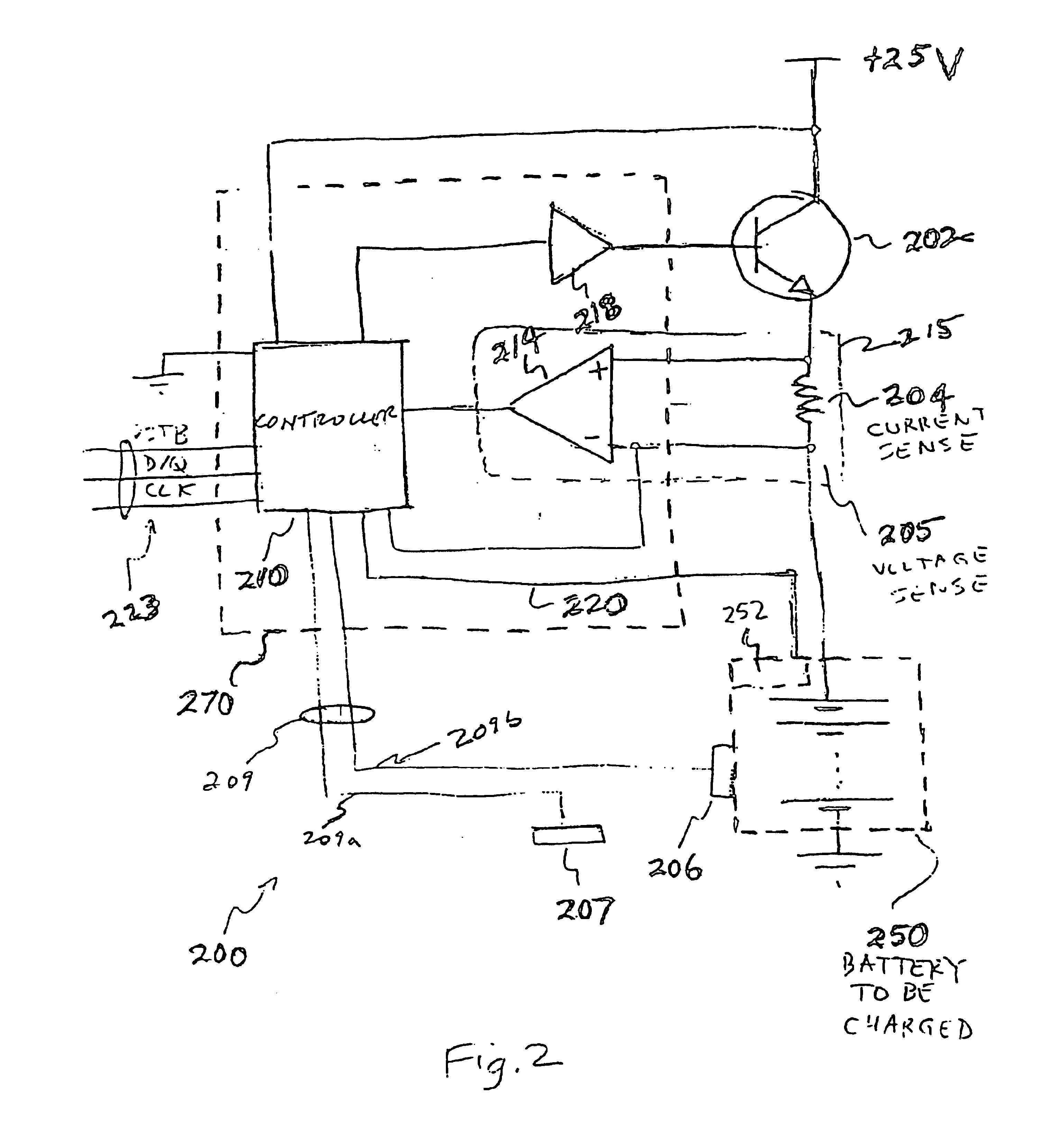
[0021]FIG. 2 is a schematic functional block diagram of a first preferred embodiment battery charger, denoted generally by reference numeral 200, connected to charge battery pack 250 with imbedded one-wire communication module 252. Battery charger 200 includes power transistor 202, current sense resistor 204, voltage sense node 205, temperature sensor 206 affixed to battery pack 250, ambient temperature sensor 207, controller 210, operational amplifier 214, power transistor driver 218, one-wire bus 220, and three-wire bus 223. Portion 270 of battery charger 200 may be formed as a single integrated circuit and provide low cost and ruggedness.

[0022]Battery charger 200 can provide battery charging up to about 20 volts with 2.5 amp currents; this demands a separate power transistor 202 for cooling. (More generally, power transistor 202 could be replaced by a DC-to-DC converter.) Battery pack 250 may have various numbers of cells and cells of various chemistries ...


PUM

PropertyMeasurementUnit
computing timeaaaaaaaaaa
timeaaaaaaaaaa
timeaaaaaaaaaa

Abstract

A battery charger with charging parameter values derived from communication with a battery pack to be charged. Communication is over a one-wire bus with battery pack transmissions in response to charger inquiries. The battery charger may be in the form an integrated circuit driving a power transistor or other controllable DC supply. A battery pack may contain a program with multiple charging currents and charging interval termination methods such as time, temperature rise, and incremental voltage polarity. A lack of communication may be invoke a default charging program or denial of access to the charger. The charger also communicates over a high-speed three-wire bus with an external computer for analysis of identification information acquired from the battery and for control of the charger.

Description

CROSS-REFERENCE TO RELATED APPLICATIONS[0001]This application is a continuation of application Ser. No. 09 / 973,155, filed Oct. 9, 2001 which is a continuation of application Ser. No. 09 / 454,275, filed on Dec. 3, 1999 now abandoned which is a continuation of application Ser. No. 09 / 178,675, filed on Oct. 26, 1998, now U.S. Pat. No. 6,018,228 which is a continuation of application Ser. No. 08 / 901,068, filed on Jul. 28, 1997, now U.S. Pat. No. 5,867,006 which is a continuation of application Ser. No. 08 / 764,285, filed Dec. 12, 1996, now U.S. Pat. No. 5,694,024 which is a continuation of application Ser. No. 07 / 957,571, filed on Oct. 7, 1992, now U.S. Pat. No. 5,592,069.[0002]U.S. patent application Ser. No. 07 / 953,906, filed Sep. 30, 1992, discloses related subject matter and is hereby incorporated by reference. This cross-referenced application is assigned to the assignee of the present application.PARTIAL WAIVER OF COPYRIGHT PURSUANT TO 1077 O.G. 22 (MAR. 20, 1987)[0003]All of the ma...

Claims


Application Information

Patent Timeline
Patent Type & Authority Patents(United States)
IPC IPC(8): G01K1/00G01K5/24G01R31/36G06F15/00G06F19/00H01M10/42H01M10/44H01M10/46H01M10/48H02J7/00
CPCG01K7/13H01M10/425H01M10/4257H01M10/48H02J7/0004H02J7/00036H02J7/00047Y02E60/10
Inventor DIAS, DONALD R.LEE, ROBERT D.
Owner MAXIM INTEGRATED PROD INC
Why Eureka
Try Eureka