Eureka AIR delivers breakthrough ideas for toughest innovation challenges, trusted by R&D personnel around the world.

Optical signal generator

Inactive Publication Date: 2005-11-29
SRI INTERNATIONAL
View PDF8 Cites 16 Cited by
  • Summary
  • Abstract
  • Description
  • Claims
  • Application Information

AI Technical Summary

Problems solved by technology

As wireless traffic increases, wireless networks are hard pressed to provide the bandwidth required to keep the traffic flowing efficiently.
The increase in traffic has caused carriers to attempt to provide bandwidths as high as a gigabit per second, but at the present, no way exists to provide such a bandwidth over a wireless network.
Giganet products are known to work typically in the megabits-per-second bandwidth range, but cannot generate a modulated millimeter-wave signal necessary for providing gigabit-per-second throughput.
Thus, the known art lacks ways of providing the throughput necessary for a modern and efficient system.

Method used


Image

  • Optical signal generator
  • Optical signal generator
  • Optical signal generator

Examples


Embodiment Construction

[0018]Embodiments of the present invention provide data-modulated millimeter-wave signals.

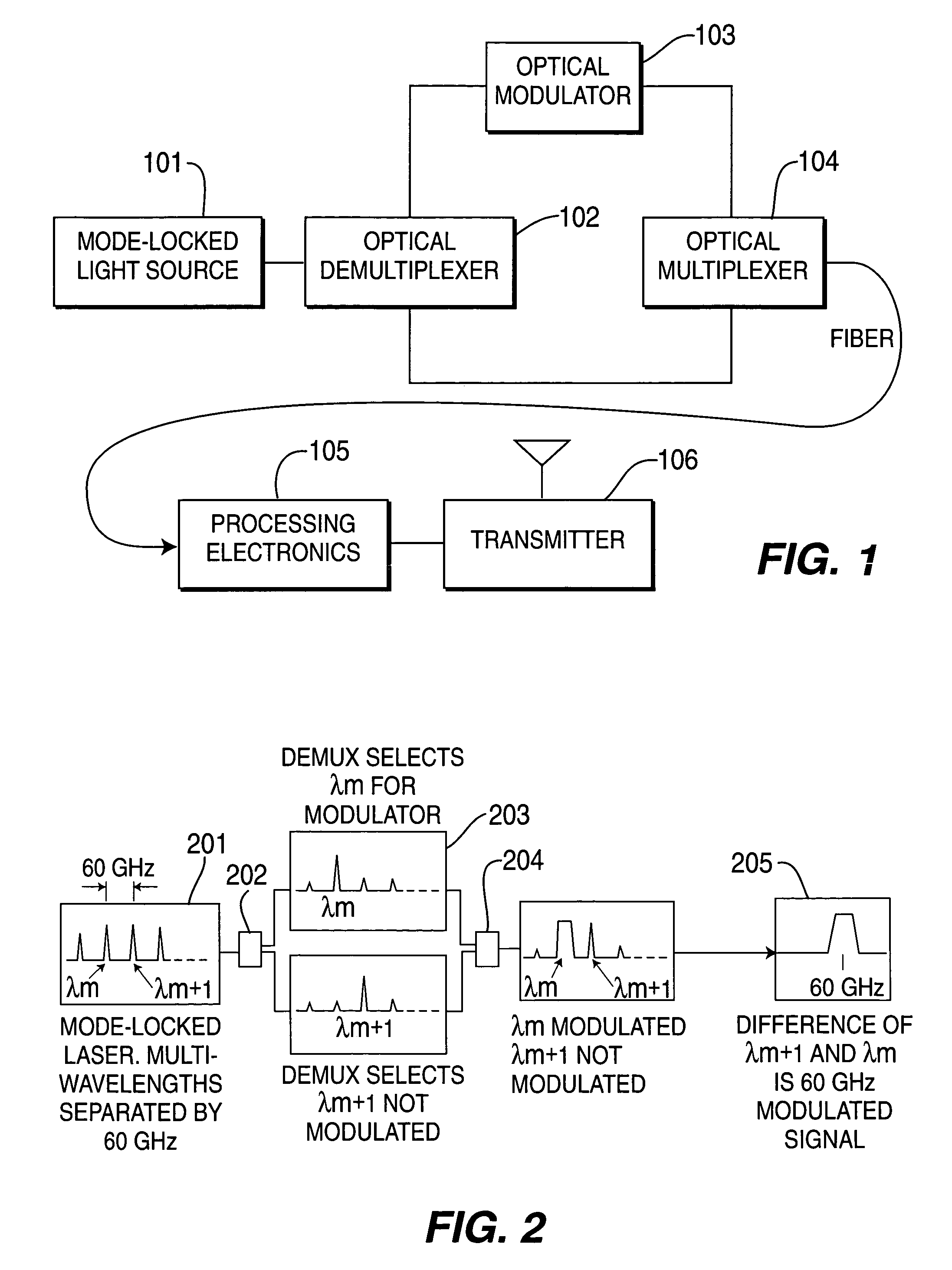
[0019]FIG. 1 is a block diagram of an apparatus according to an embodiment of the present invention. In this figure, mode-locked light source 101 produces light at various wavelengths that are all harmonically related to one another. The mode-locked light source is typically a mode-locked semiconductor laser, examples of which can be found in U.S. Pat. No. 6,018,536, filed on Feb. 9, 1999, the entirety of which is hereby incorporated by reference. These mode-locked semiconductor lasers are capable of emitting discrete wavelengths of light separated by a distance on the order of approximately 15 mm.

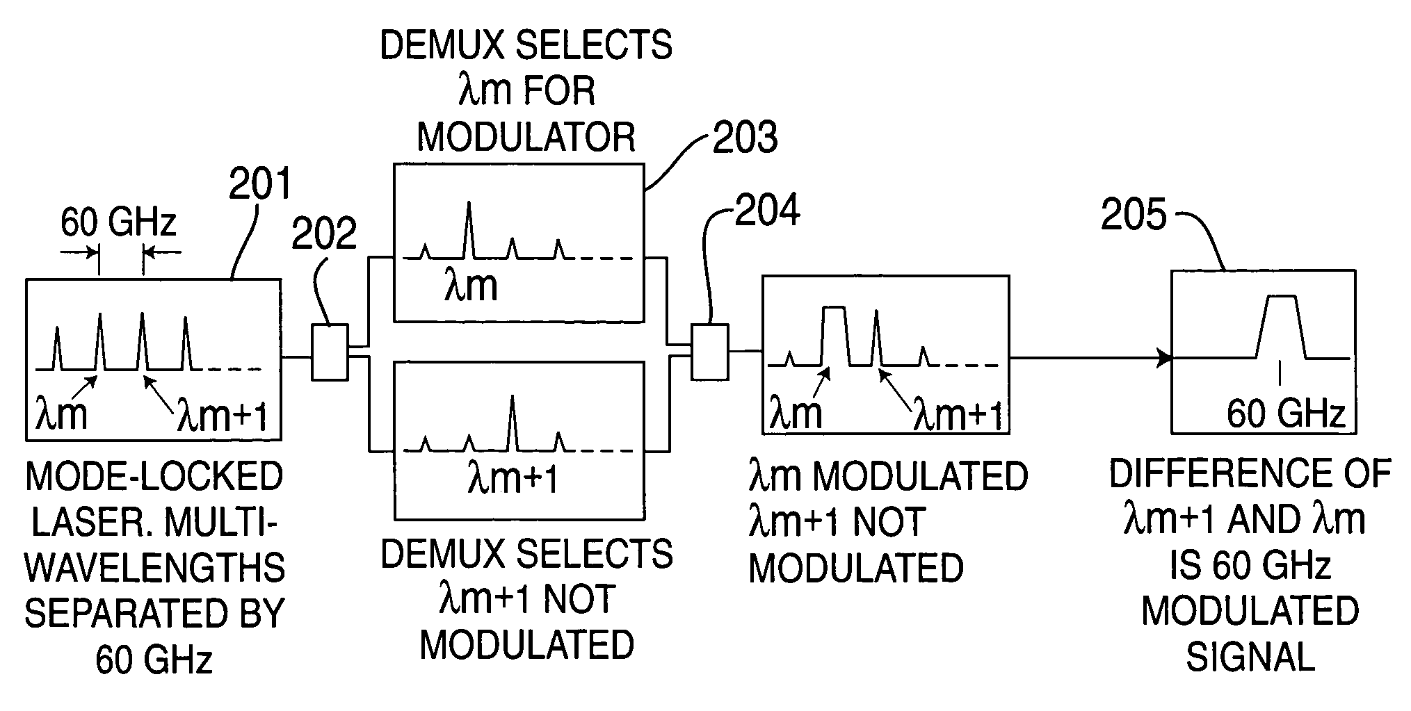
[0020]Once the light is emitted, it is coupled into optical demultiplexer 102 that acts as a wavelength filter and separator. In one embodiment, optical demultiplexer 102 can select a first wavelength for a first path, a second wavelength for a second path, and can discard the remaining wavelengths.

[0...


PUM


Abstract

An apparatus for optically generating signals comprises a mode-locked optical radiation source that generates mode-locked optical radiation with emitted modes separated by approximately 10 to approximately 300 GHz. Coupled to the optical radiation source is an optical demultiplexer with a demultiplexer input, a first demultiplexer output, and a second demultiplexer output, the demultiplexer input being coupled to said mode-locked radiation source. Additionally, the apparatus comprises an optical modulator having a modulator input and a modulator output, the modulator input being coupled to the first demultiplexer output, and an optical multiplexer having a first multiplexer input, a second multiplexer input, and a multiplexer output, the first multiplexer-input being coupled to the modulator output, the second multiplexer input being coupled to said second demultiplexer output.

Description

CROSS REFERENCE TO RELATED APPLICATIONS[0001]The present application claims priority to United States Provisional Application No. 60 / 147,941, filed Aug. 5, 1999, which is hereby incorporated by reference.FIELD OF THE INVENTION[0002]The present invention relates to wireless communications systems. More particularly, the present invention relates to a method and apparatus for generating optical signals at high bandwidth.BACKGROUND OF THE INVENTION[0003]As wireless traffic increases, wireless networks are hard pressed to provide the bandwidth required to keep the traffic flowing efficiently. The increase in traffic has caused carriers to attempt to provide bandwidths as high as a gigabit per second, but at the present, no way exists to provide such a bandwidth over a wireless network.[0004]An example of a known system that provides relatively high bandwidth is provided by a company called Giganet, Inc. Giganet products are known to work typically in the megabits-per-second bandwidth ra...

Claims


Application Information

Patent Timeline
IPC IPC(8): H01S3/098H01S5/065H01S5/10H01S5/223H01S5/343H04B10/04H04B10/12
CPCB82Y20/00H01S5/1071H04B10/25752H01S3/1118H01S5/0657H01S5/2231H01S5/34306H04B2210/006
Inventor PAGLIONE, ROBERT WAYNEROSEN, ARYEGRIFFEL, GIORAPERLOW, STEWART MARK
Owner SRI INTERNATIONAL
Why Eureka
Eureka Blog
Learn More