Diagnostic system and method for electric leak detecting device

a detection system and detection device technology, applied in the direction of electric devices, emergency protective arrangements for limiting excess voltage/current, nuclear elements, etc., can solve the problems of electric leak detection, electric current from a direct current power supply (battery) leakage to the vehicle body, and difficulty in detecting electric leakag

Inactive Publication Date: 2005-11-29
TOYOTA JIDOSHA KK
View PDF21 Cites 36 Cited by
  • Summary
  • Abstract
  • Description
  • Claims
  • Application Information

AI Technical Summary

Benefits of technology

[0011]It is an object of the invention to provide a diagnostic system which performs a diagnosis on whether an electric leak detecting device, that detects an electric leak (a real electric leak and a simulated electric leak), operates reliably even when a common mode voltage fluctuates, in a power supply unit for a vehicle.

Problems solved by technology

There are cases where an electric current from a direct current power supply (battery) leaks to a vehicle body (a ground fault occurs) due to causes such as a contact failure of a bus line.
Therefore, an electric leak is detected by an electric leak detecting device.
However, with the electric leak detecting devices disclosed in Japanese Patent Laid-Open Publication No. 8-70503 and Japanese Patent Laid-Open Publication No.8-226950, it is difficult to detect an electric leak when an electric potential (common mode voltage) of the battery terminal with respect to an electric potential of a vehicle body fluctuates.
Since a signal for detecting a simulated electric leak fluctuates, it is difficult to perform an accurate self-diagnosis.
Therefore, it is difficult to accurately perform a diagnosis of the operating performance of the electric leak detecting circuit disclosed in the publication.

Method used


Image

  • Diagnostic system and method for electric leak detecting device
  • Diagnostic system and method for electric leak detecting device
  • Diagnostic system and method for electric leak detecting device

Examples


first embodiment

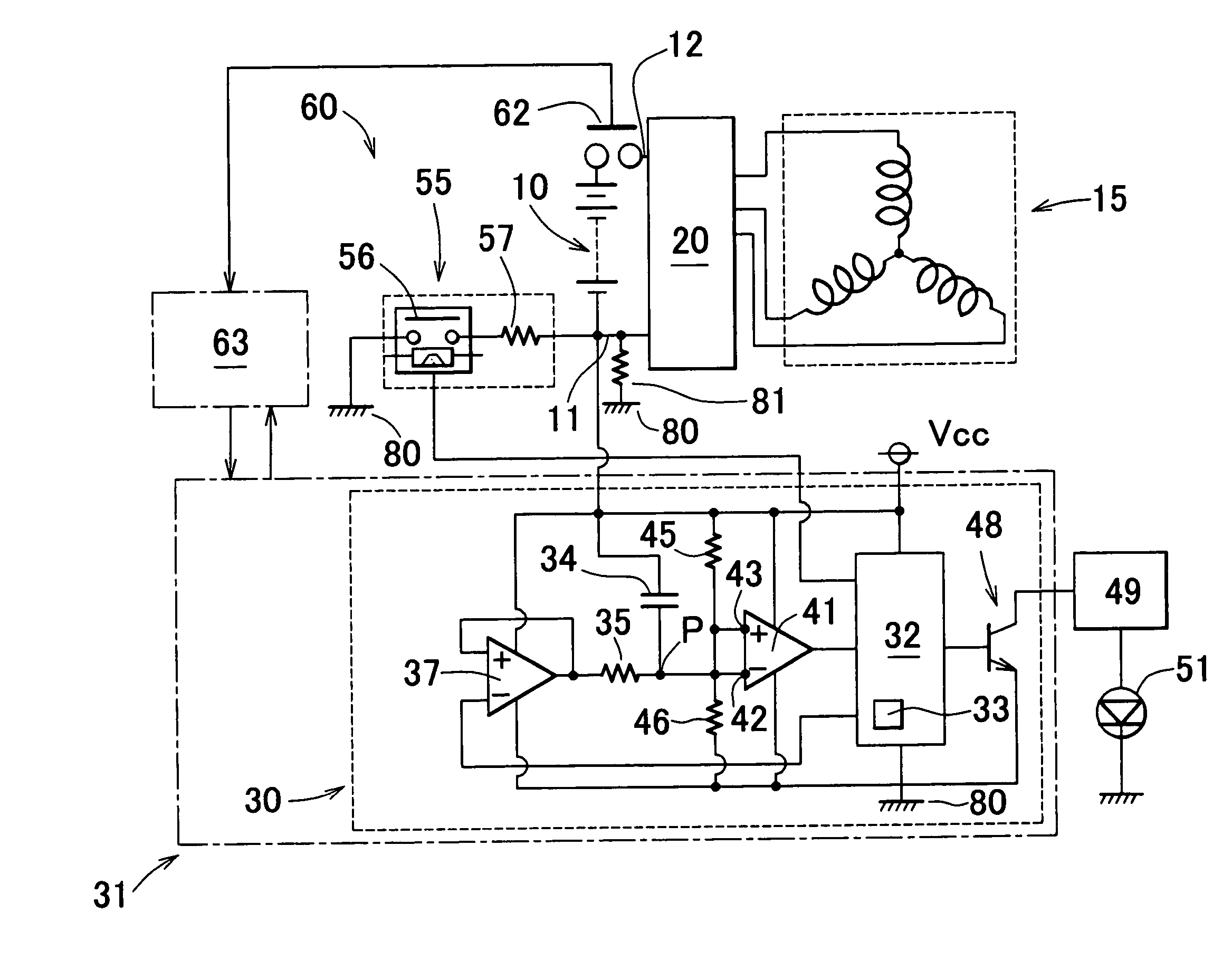
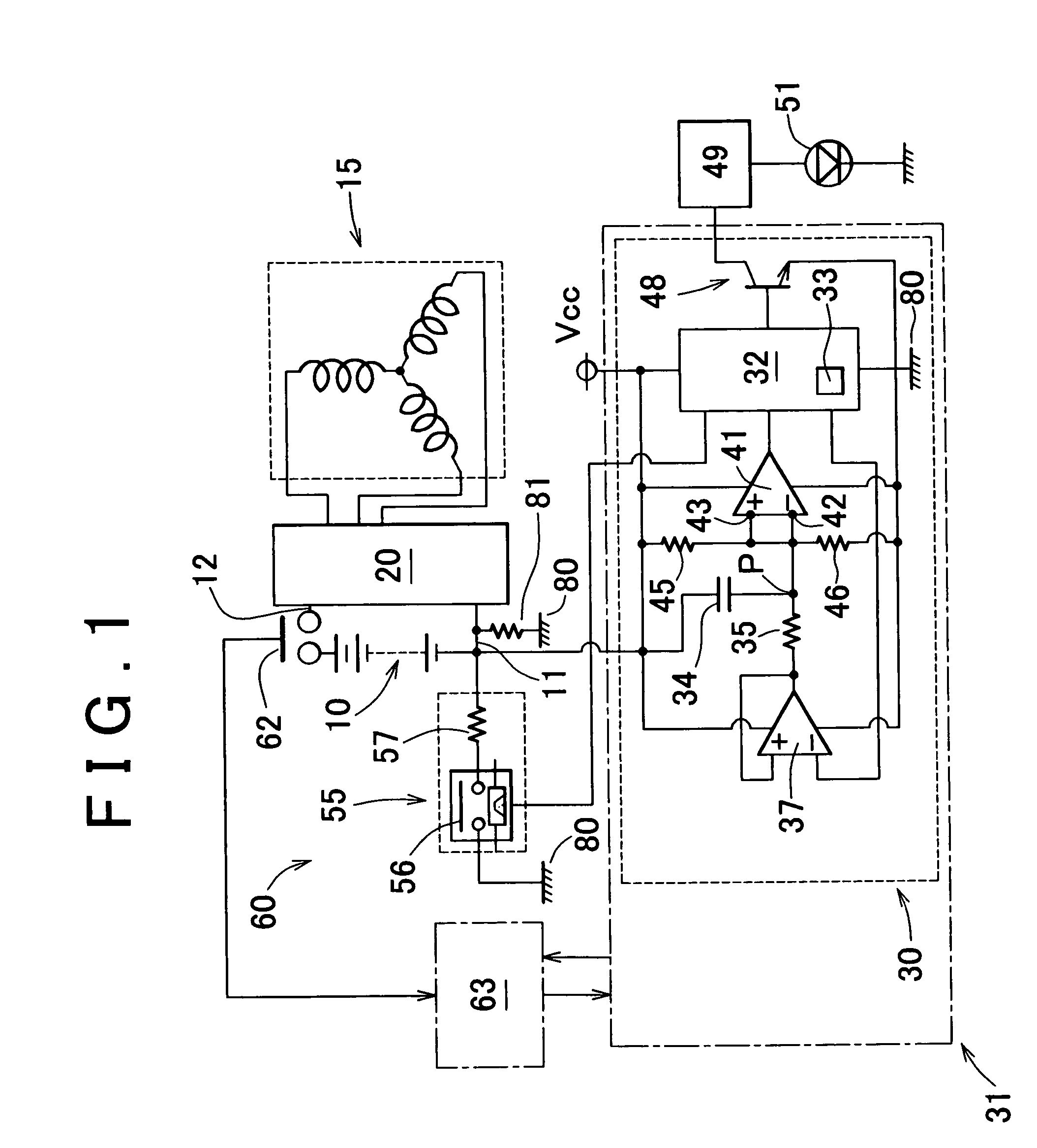
[0034]the invention will be described. As shown in FIG. 1, a power supply unit of a hybrid vehicle includes a battery (direct current power supply) 10, a three-phase alternating current motor (hereinafter, simply referred to as a “motor”) 15 which is driven by the battery 10, and an electric power converting device (hereinafter, referred to as an “inverter”) 20 which is provided between the battery 10 and the motor 15 and which converts electric power form a direct current to an alternating current. The power supply unit further includes an electric leak detecting circuit 30 and a simulated electric leak generating device 55. The electric leak detecting device (detecting circuit) 30 constitutes a part of a battery ECU 31, and includes a transmission circuit 32, a buffer 37, a comparator 41, a transistor 48 and the like. The transmission circuit 32 includes a transmission portion 33 and a plurality of terminals. After a predetermined time has elapsed since an ignition key is turned t...

second embodiment

[0051]An operation of the second embodiment will be described with reference to FIG. 4. In this description, the description of the electric leak detecting device 30 and the description of the simulated electric leak generating device 55 will be used where appropriate.

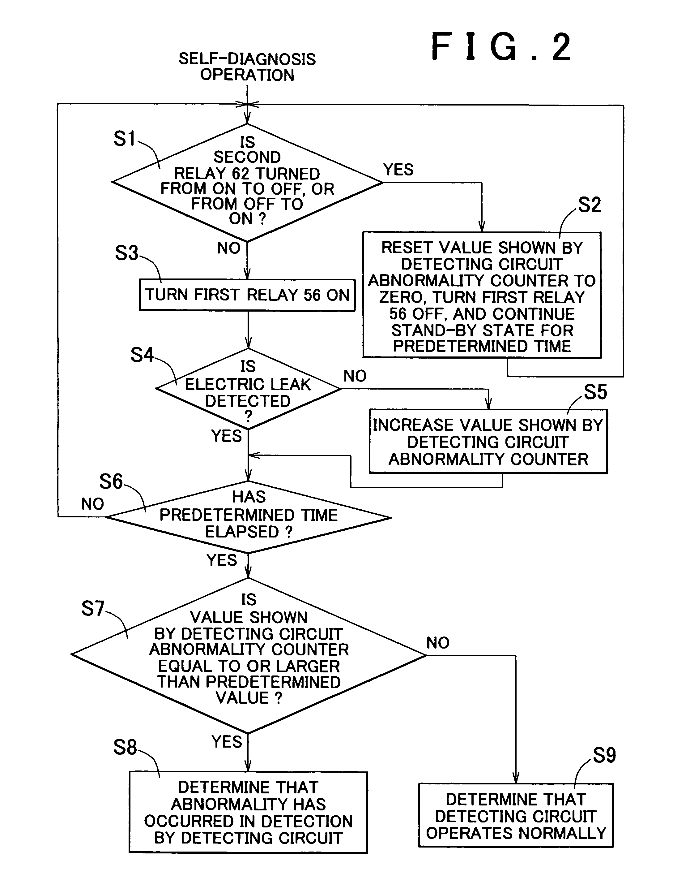
[0052]In S11, it is determined whether the relay 90 is turned from ON to OFF, or from OFF to ON. When it is determined that the relay 90 is turned from ON to OFF, or from OFF to ON, the value shown by the electric leak counter in the transmission circuit 32 is reset to zero, and a stand-by state is continued for a predetermined time. Then, S11 is performed again, and it is determined whether the relay 90 is turned from ON to OFF, or from OFF to ON, again. When it is determined that the relay 90 is not turned from ON to OFF, or from OFF to ON, S13 is then performed and the electric leak detecting device 30 detects whether an electric leak has occurred in the bus line 12. When an electric leak, that is, a ground fault, i...


PUM


Abstract

A power supply unit includes a battery, a motor which is driven by the battery, an electric power converting device which is provided between the battery and the motor, a simulated electric leak generating device which generates an electric leak state between the battery and a vehicle body, and an electric leak detecting device which detects a simulated electric leak. A diagnostic system which performs a diagnosis of operating performance of the electric leak detecting device includes an opening/closing device which connects/disconnects the electric power converting device to/from the battery, and an opening/closing detecting device which detects opening/closing of the opening/closing device and which outputs a result of detection to the simulated electric leak generating device and the electric leak detecting device. When opening/closing of the opening/closing device is detected by the opening/closing detecting device, both generation of a simulated electric leak and detection of an electric leak are retried.

Description

INCORPORATION BY REFERENCE[0001]The disclosure of Japanese Patent Application No. 2003-153219 filed on May 29, 2003 including the specification, drawings and abstract is incorporated herein by reference in its entirety.BACKGROUND OF THE INVENTION[0002]1. Field of the Invention[0003]The invention relates to a diagnostic system and method for an electric leak detecting device in a power supply unit having an electric leak detecting function.[0004]2. Description of the Related Art[0005]There are cases where an electric current from a direct current power supply (battery) leaks to a vehicle body (a ground fault occurs) due to causes such as a contact failure of a bus line. Therefore, an electric leak is detected by an electric leak detecting device. When an electric leak is detected, an alarm lamp of a meter lights up, or the like.[0006]According to Japanese Patent Laid-Open Publication No. 8-70503, in order to detect an electric leak, a rectangular wave is input in between a battery an...

Claims


Application Information

Patent Timeline
Patent Type & Authority Patents(United States)
IPC IPC(8): G01R31/02B60L1/00B60L3/00B60R16/02G01M17/00G01R31/00H02H3/05H02H3/16H02H7/00
CPCB60K6/48B60L3/0023B60L3/0069G01R31/025Y02T10/6221G01R31/52H02H1/0007H02H3/08H02H3/17Y02T10/62
Inventor KITO, YUJIFUJITA, HIROSHIKATO, KAZUYUKIASAI, TOSHIHARU
Owner TOYOTA JIDOSHA KK
Why Eureka
Try Eureka