Integrated circuits for multi-tasking support in single or multiple processor networks

a multi-tasking, integrated circuit technology, applied in the direction of program control, program initiation/switch, architecture with multiple processing units, etc., can solve problems such as temporal indeterminacy

Inactive Publication Date: 2005-11-29
MBDA UK
View PDF18 Cites 4 Cited by
  • Summary
  • Abstract
  • Description
  • Claims
  • Application Information

AI Technical Summary

Benefits of technology

[0011]The “Butler chips” proposed in the present invention can fulfil the role of the KEC and also absorb CEC functions where feasible. One advantage of using the “Butler chip” in the above context is the removal of the aforementioned temporal indeterminacy by eliminating the need for stim servers. It also facilitates a more flexible priority and poll set scheme.
[0015]The provision of multiple stim-wait channels allows each activity to put itself into a condition where it selectively waits for stimuli from a plurality of sources eg. from its associated CPU, a peripheral device or from another “Butler chip”.
[0024]The invention offers many advantages. The design can be easily implemented in different technologies because it is not dependent on critical timing parameters. There are no clock signals to distribute and consequently no clock-skew or set-up and hold violation problems. All of the circuitry is related to the application, using minimum circuitry per function. Furthermore, the asynchronous circuitry has non-demanding power-supply requirements particularly if CMOS technology is employed. The chip design can be analysed for correctness by formal mathematical methods and manufactured devices may be tested, in isolation, to achieve full fault coverage.
[0027]In the example of a multiprocessor system, each processor has its own associated “Butler chip” and connections are made between “Butler chips”. A request for scheduling any task is always registered with a processor's own “Butler chip”. Where the task resides on a different processor, “Butler chips” communicate directly and schedule the relevant task on the destination processor when its turn arrives. This avoids the need to unnecessarily interrupt any task running on the destination processor, thereby providing an efficient, temporally deterministic operation.

Problems solved by technology

Disadvantageously, this arrangement introduces temporal indeterminacy because the stim servers run and impede the progress of application level activities.

Method used


Image

  • Integrated circuits for multi-tasking support in single or multiple processor networks
  • Integrated circuits for multi-tasking support in single or multiple processor networks
  • Integrated circuits for multi-tasking support in single or multiple processor networks

Examples


Embodiment Construction

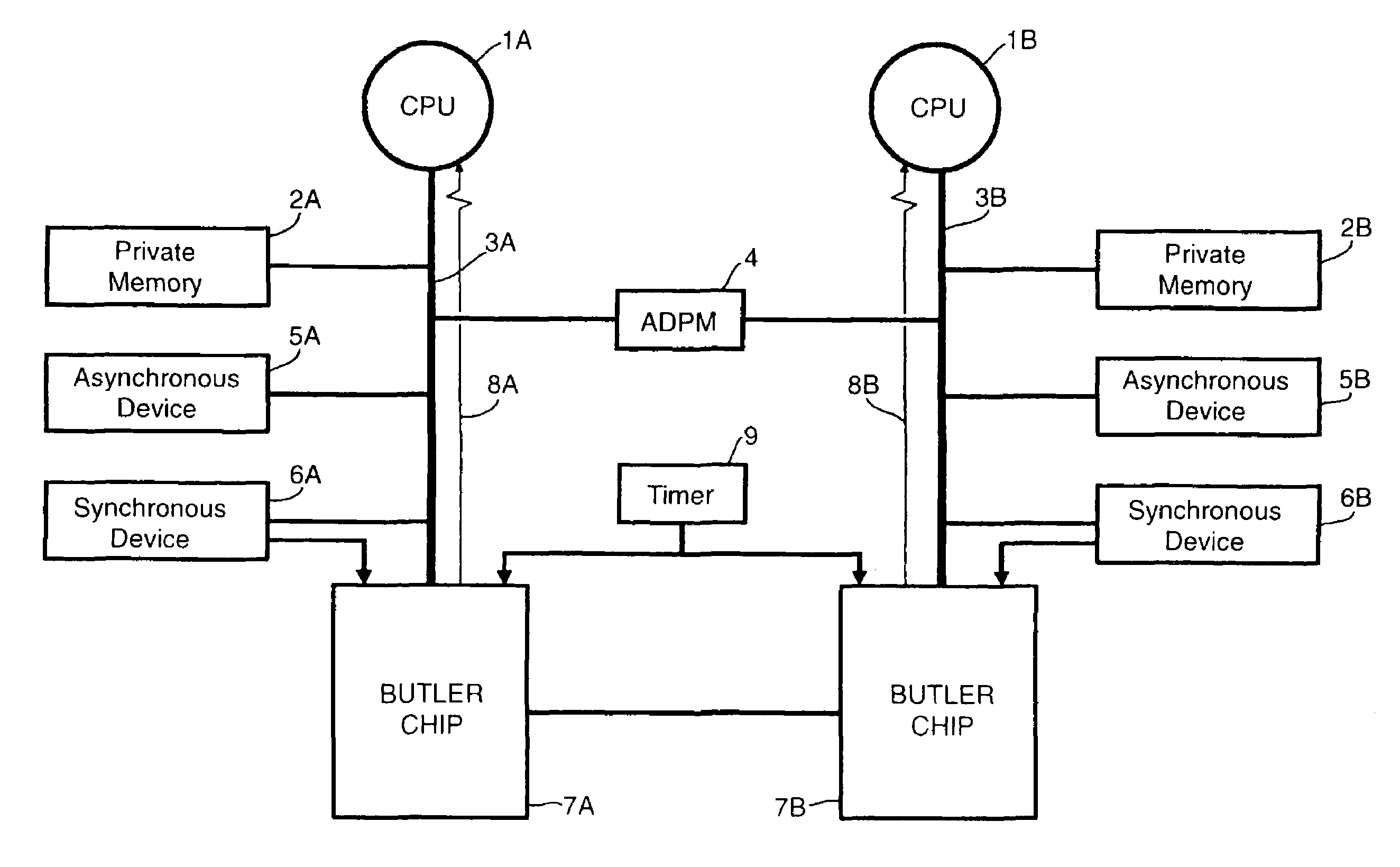
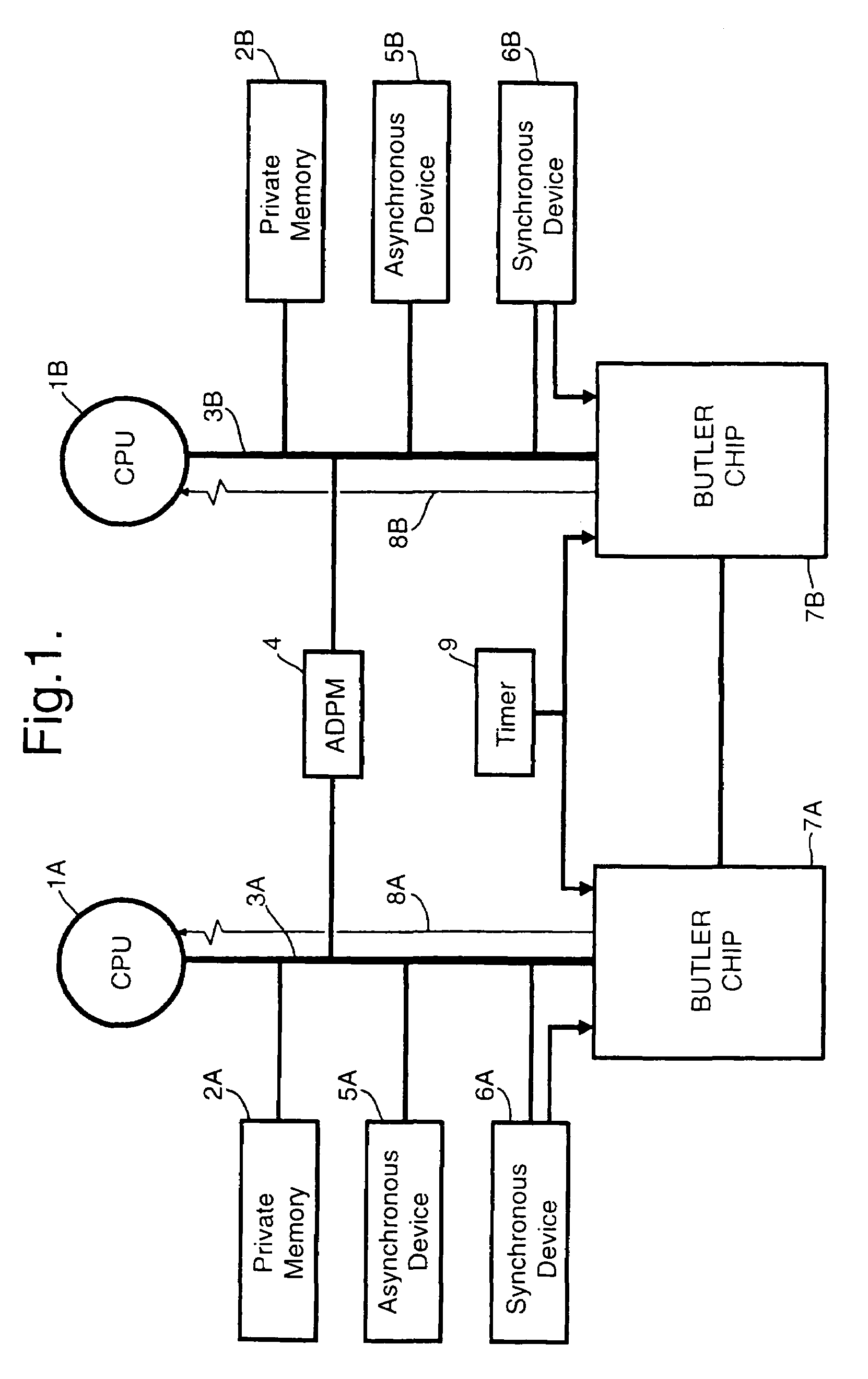
[0034]In FIG. 1 a dual processor system comprises two central processing units (CPU) 1A, 1B, each CPU being linked to a private memory 2A, 2B via a data bus 3A, 3B. The CPU's 1A, 1B are linked to each other by means of an asynchronous dual port memory (ADPM) 4. Each CPU 1A, 1B also has access to asynchronous devices (peripherals) 5A, 5B, synchronous devices (ie peripherals which can generate an external stimulus) 6A, 6B and an associated “Butler chip”7A, 7B respectively. The “Butler chips”7A, 7B are connected with one another.

[0035]An interrupt line 8A, 8B, runs from each “Butler chip”7A, 7B to its associated CPU 1A, 1B. This can be used to trigger task switching when using pre-emptive scheduling or to indicate a watch-dog timer overrun when using co-operative scheduling.

[0036]Each “Butler chip” may be provided with a standard memory interface for connection to its associated processor. Conveniently, this could comprise a 16-bit bi-directional data bus, three address lines and three...


PUM


Abstract

An integrated circuit (7A) for multitasking support for processing unit (1A) holds control variables for each task (or activity) to run on its associated processor (1A) and identifies the next task that should run. The circuit (7A) employs level-driven, clock free ripple logic and is configured as a two dimensional array of “tiles”, each tile being composed of simple logic gates and performing a dedicated function. The circuit has particular application to asynchronous multiple processor networks.

Description

BACKGROUND OF THE INVENTION[0001]1. Field of the Invention[0002]This invention relates to integrated circuits and particularly, though not exclusively to integrated circuits for use in single or multi-processor systems.[0003]2. Discussion of Prior Art[0004]One object of the invention is to provide an integrated circuit, (to be referred to herein as a “Butler Chip”) which is capable of directly supporting the shared data and multi-tasking concepts of real-time networks in the context of single or multi-processor systems.[0005]A further object is to provide a more deterministic (in the temporal sense) execution environment so as to eliminate some aspects of pessimistic timing analysis at the fundamental level of computer operation.[0006]For a better understanding of an application of the “Butler Chip” to be described herebelow, reference is made to our co-pending Patent Application WO91 / 16681 (now U.S. Pat. No. 5,469,549). Therein, two Central Processing Units (CPU) are able to intera...

Claims


Application Information

Patent Timeline
Patent Type & Authority Patents(United States)
IPC IPC(8): G06F9/48G06F15/80
CPCG06F9/4881G06F15/8023
Inventor CAMPBELL, ERIC RSIMPSON, HUGO R
Owner MBDA UK
Why Eureka
Try Eureka