Confluent exhaust nozzle

a technology of exhaust nozzle and confluent nozzle, which is applied in the direction of vessel construction, marine propulsion, aircraft navigation control, etc., can solve the problems of increasing increasing the complexity, weight and cost of the engine, and no longer using the auxiliary outlet itsel

Active Publication Date: 2005-12-06
THE NORDAM GRP
View PDF26 Cites 83 Cited by
  • Summary
  • Abstract
  • Description
  • Claims
  • Application Information

AI Technical Summary

Problems solved by technology

Variable area nozzles permit adjustment of the aerodynamic performance of the engine which correspondingly increases complexity, weight, and cost of the engine.
Various types of thrust reversers are found in the engine nacelle and further increase complexity, weight, and cost of the engine.
However, the auxiliary outlet itself is no longer utilized following takeoff operation, and may introduce base drag thereat during the remainder of the aircraft flight, including the typically long duration cruise operation.

Method used


Image

  • Confluent exhaust nozzle
  • Confluent exhaust nozzle
  • Confluent exhaust nozzle

Examples


Embodiment Construction

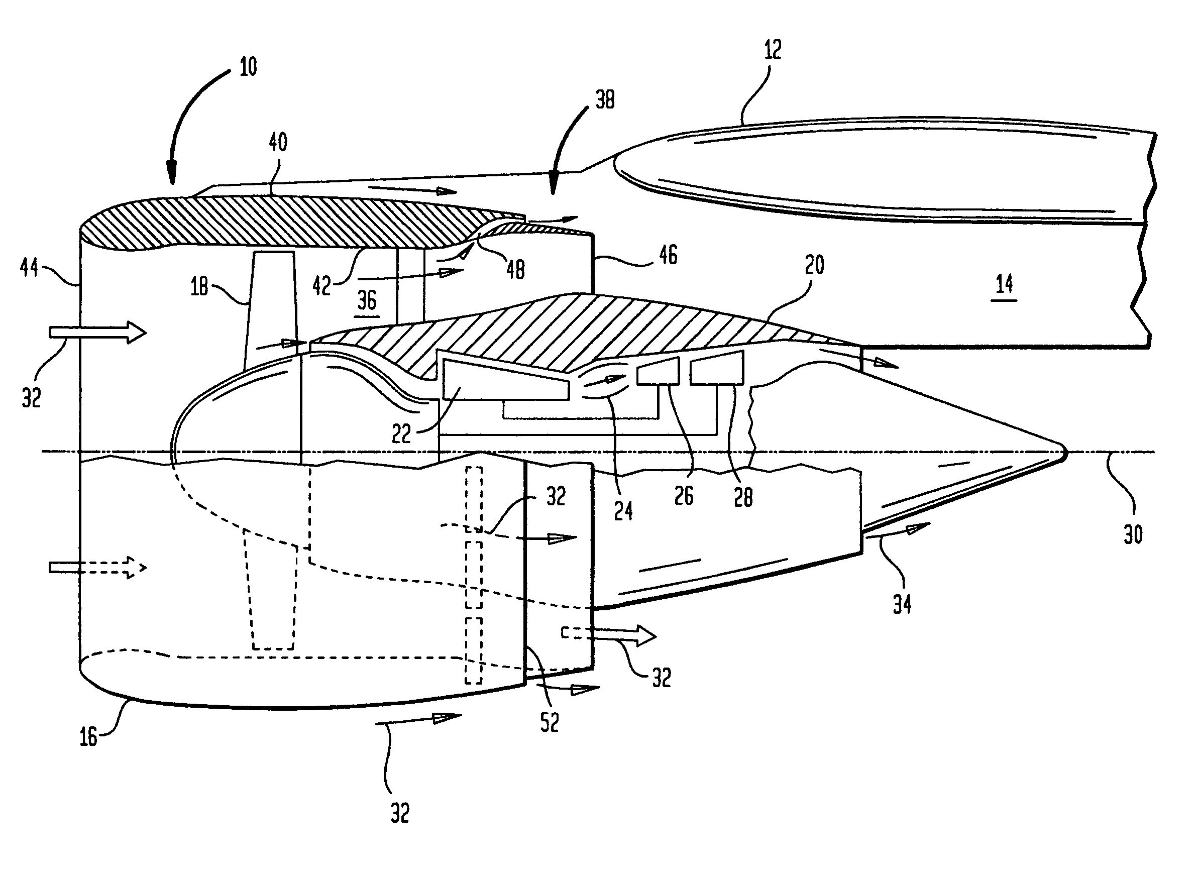
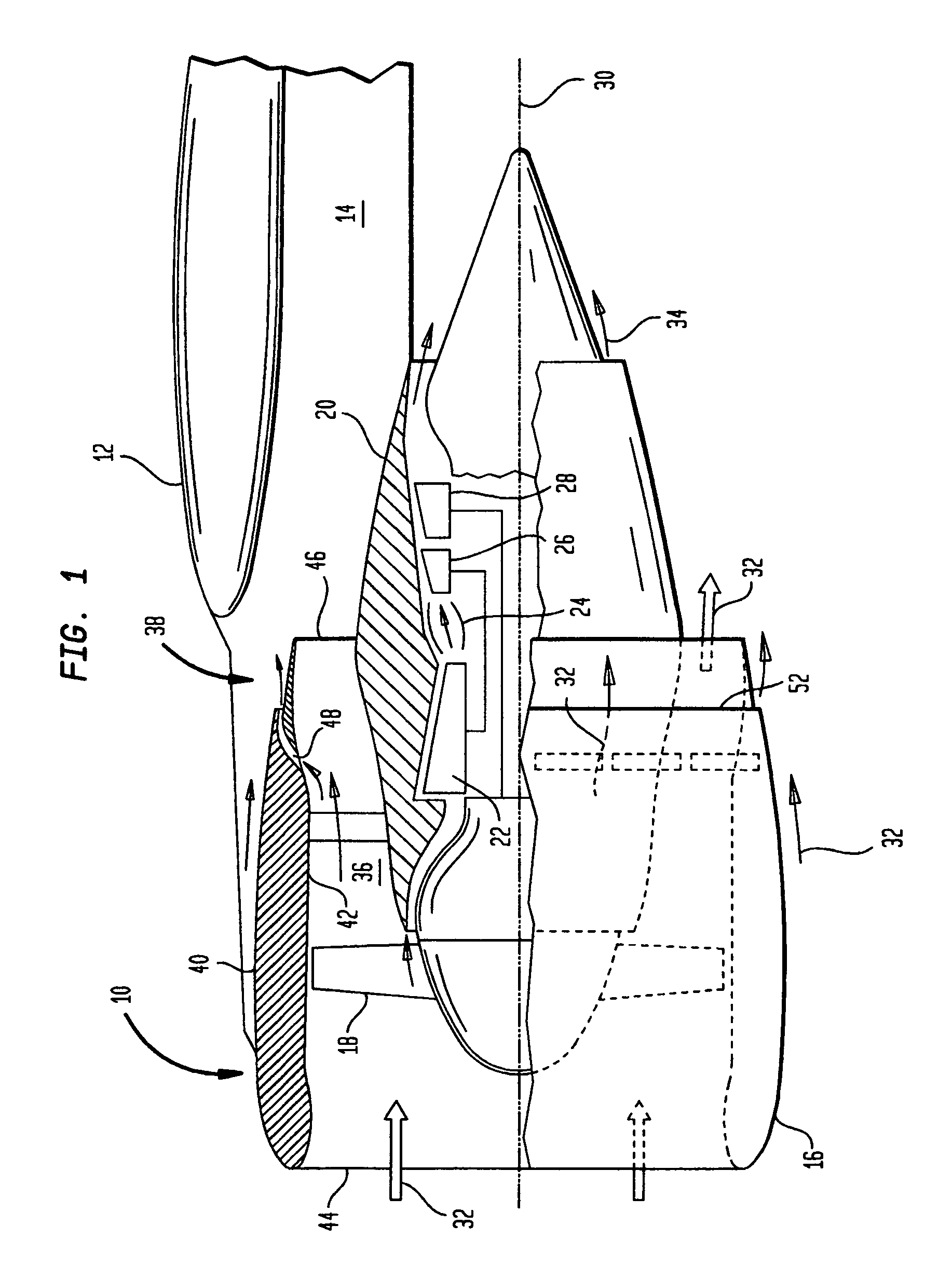
[0020]Illustrated in FIG. 1 is a turbofan aircraft gas turbine engine 10 suitably mounted to the wing 12 of an aircraft by a supporting pylon 14. Alternatively, the engine could be mounted to the fuselage of the aircraft if desired.

[0021]The engine includes an annular fan nacelle 16 surrounding a fan 18 which is powered by a core engine surrounded by a core nacelle or cowl 20. The core engine includes in serial flow communication a multistage axial compressor 22, an annular combustor 24, a high pressure turbine 26, and a low pressure turbine 28 which are axisymmetrical about a longitudinal or axial centerline axis 30.

[0022]During operation, ambient air 32 enters the fan nacelle and flows past the fan blades into the compressor 22 for pressurization. The compressed air is mixed with fuel in the combustor 24 for generating hot combustion gases 34 which are discharged through the high and low pressure turbine 26,28 in turn. The turbines extract energy from the combustion gases and powe...


PUM


Abstract

A gas turbine engine exhaust nozzle includes a nacelle having an inlet and main outlet at opposite ends, and a main duct extending therebetween. A secondary bypass duct extends radially through the nacelle upstream of the main outlet and includes an unobstructed secondary inlet joined to the main duct, and a secondary outlet surrounding the main outlet for collectively discharging exhaust flow in confluent streams.

Description

[0001]This application claims the benefit of U.S. Provisional Application No. 60 / 450,121; having filing date Feb. 26, 2003.BACKGROUND OF THE INVENTION[0002]The present invention relates generally to turbofan aircraft engines, and, more specifically, to exhaust nozzles therefor.[0003]A typical turbofan aircraft engine includes a fan powered by a core engine. The core engine includes a surrounding cowl or nacelle, and the fan includes a corresponding cowl or nacelle at the forward end of the core engine which extends aft either in part or fully thereover.[0004]The fan nacelle is spaced radially outwardly from the core nacelle to define an annular bypass duct therebetween. During operation, the core engine powers the fan which pressurizes ambient air to produce propulsion thrust in the fan air bypassing the core engine and discharged from the fan exhaust nozzle.[0005]A portion of the fan air is channeled into the core engine wherein it is pressurized and mixed with fuel for generating ...

Claims


Application Information

Patent Timeline
Patent Type & Authority Patents(United States)
IPC IPC(8): F01DF02K1/00F02K1/06F02K1/34F02K1/38F02K1/46F02K1/70F02K3/02
CPCF02K1/06F02K1/34F02K1/46F02K1/70F02K3/06F02K3/077
Inventor LAIR, JEAN-PIERRE
Owner THE NORDAM GRP
Why Eureka
Try Eureka