Lane maker

a technology of traffic control cones and lane makers, which is applied in the direction of roads, instruments, construction, etc., can solve the problems of more restrictive control, more time and labor required to set up the barrier, and the difficulty of bringing the cones to the site and setting them up,

a technology of traffic control cones and lane makers, which is applied in the direction of roads, instruments, construction, etc., can solve the problems of more restrictive control, more time and labor required to set up the barrier, and the difficulty of bringing the cones to the site and setting them up,

US6971329B1Inactive Publication Date: 2005-12-06STEWART ROBIN HARDIE

Image

  • Lane maker
  • Lane maker
  • Lane maker

Examples


Embodiment Construction

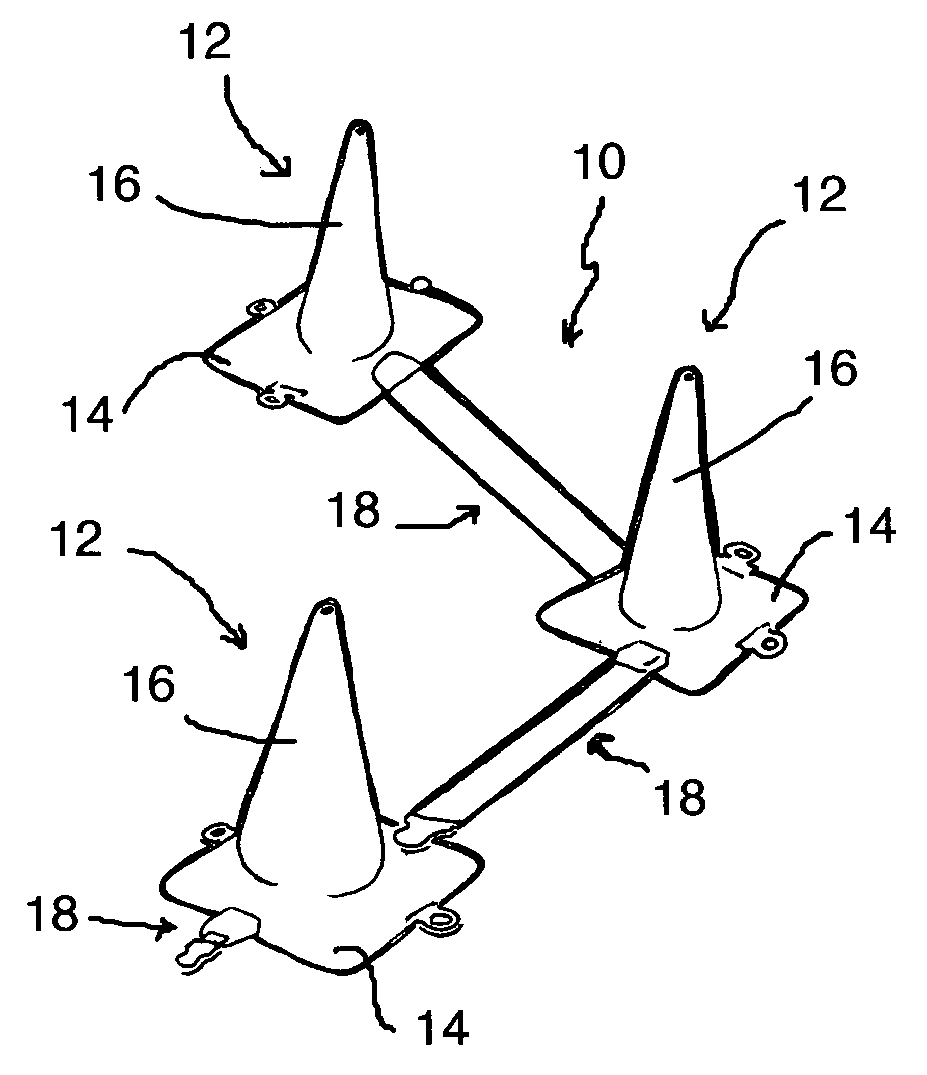
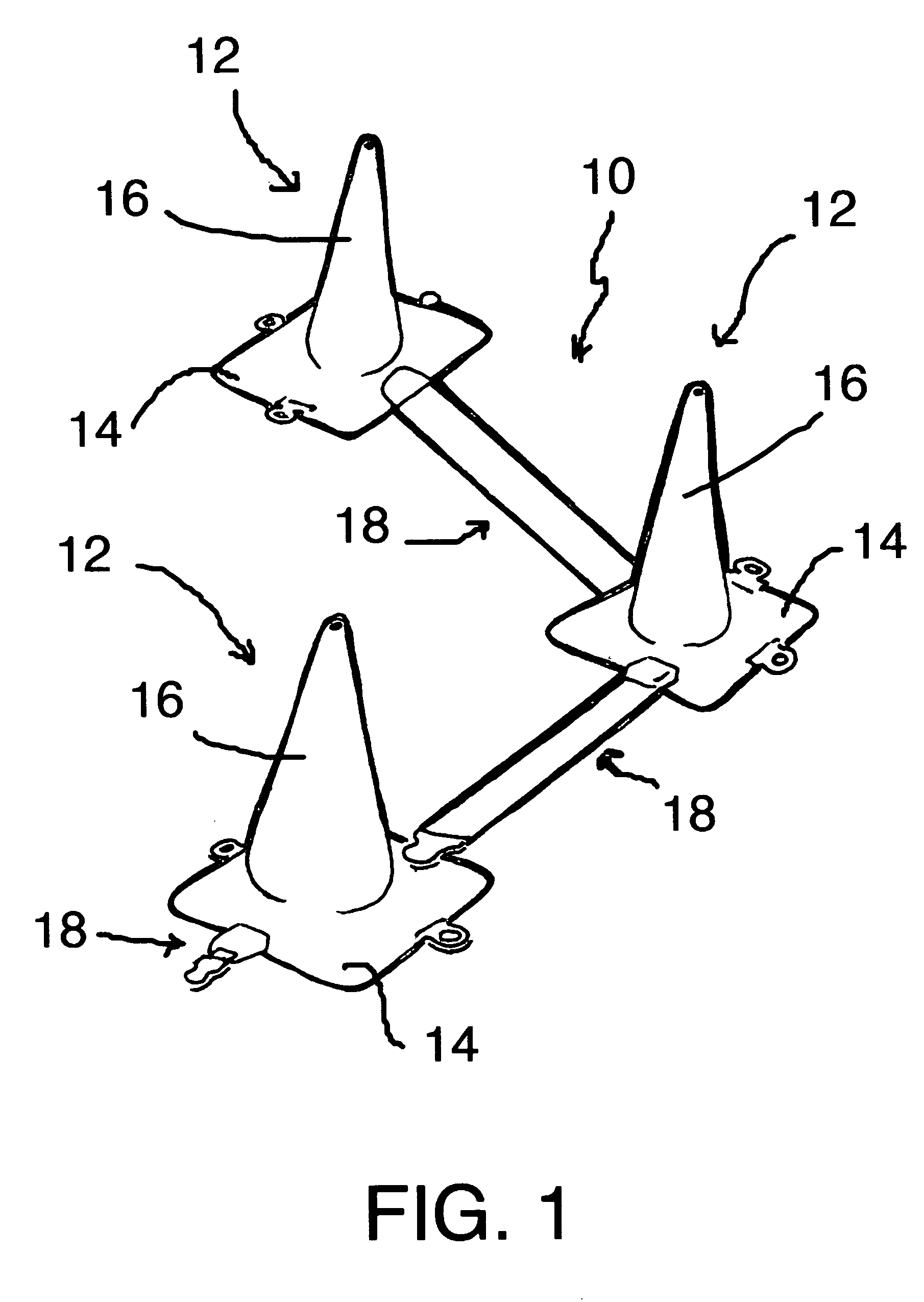
[0043]Referring now to the FIG. 1, a traffic control lane maker 10 comprises a plurality of traffic cones 12 arranged and interconnected together so as to create a lane designating boundary for a new traffic pattern. The boundary is physically delineated to be more clearly and positively seen.

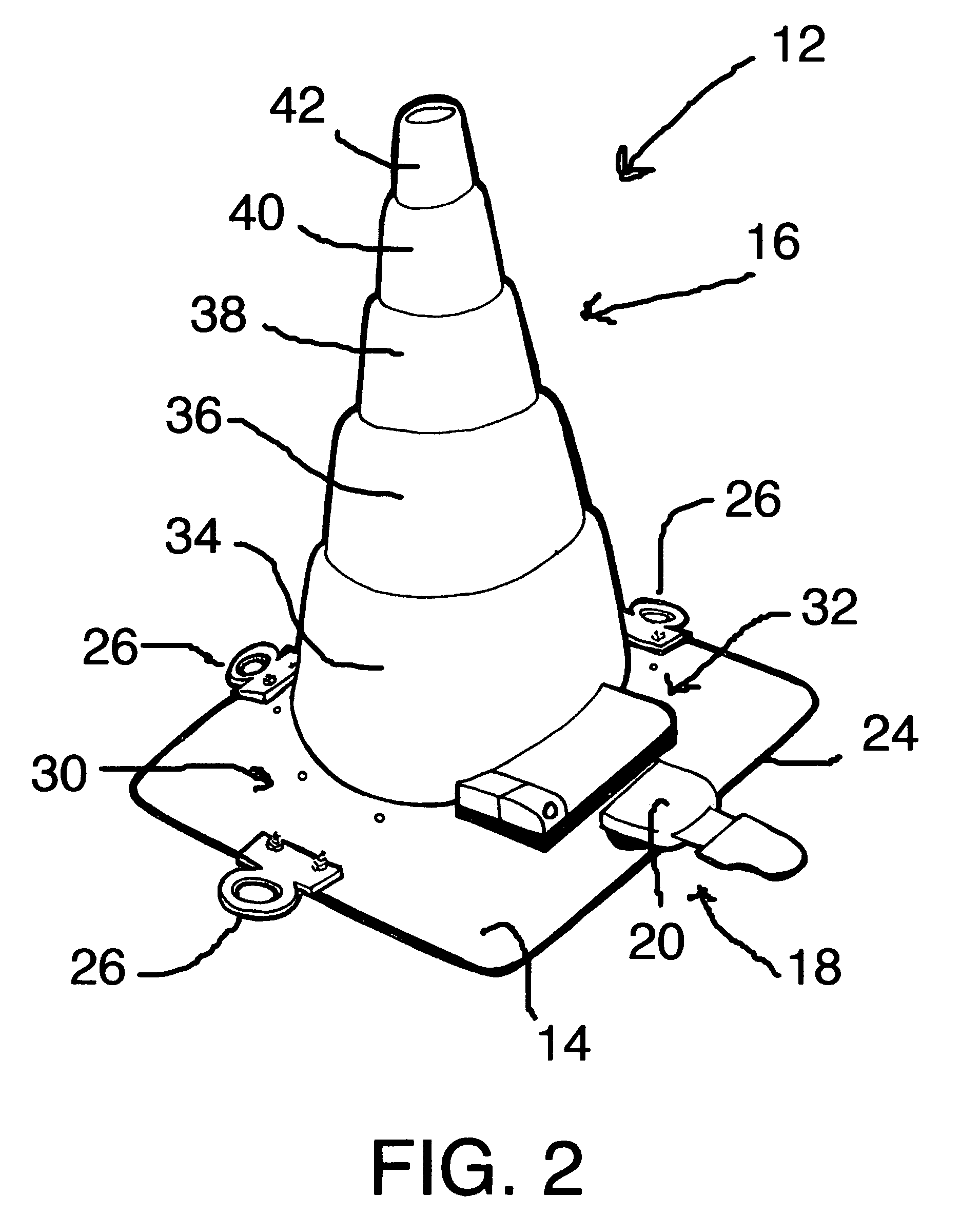
[0044]Each of traffic cones 12 comprise a substantially square, relatively planar base 14 and a generally conical cap 16. Preferably, traffic cones 12 are made of the usual traffic cone materials and, in the basic embodiment of the invention, are colored in the usual manner. It is within the scope of the invention, however, to make them of other materials and / or other colors. For example, they may be color coded to indicate the type of activity from which the traffic is being separated: (1) red for emergencies, such as stalled cars, collapsed bridges or roadways, downed electrical lines, etc.; orange as now usually associated with official Department of Transportation road repairs; green for ut...


PUM


Abstract

A collapsible traffic control cone includes a lane marker for delineating lines of demarcation between lanes approved for traffic flow and areas where traffic is prohibited. When in use, the lane marker extends from a rotatable housing mounted on one of the cones and is releasably attached to an anchor on an adjacent cone. The lane marker is a flat, highly reflective web which lies flat on the roadway between the cones. In the event of a cone being tipped over from its base or when not in use, the lane marker retracts into its housing. A light responsive to oncoming traffic is also provided.

Description

RELATED APPLICATIONS[0001]Benefit of Provisional Application Ser. No. 60 / 455,579, Titled “Delineator Safety Attachment System [Temporary Lane Maker]”, filed Mar. 19, 2003, is hereby claimed.BACKGROUND OF THE INVENTION[0002]1. Field of the Invention[0003]This invention relates to a collapsible traffic control cone with a rotatable lane marker for delineating lines of demarcation between lanes approved for traffic flow and areas where traffic is prohibited. A plurality of cones become a new lane maker, when they are connected together by releasably attaching the rotatable lane marker of each cone to an anchor on its adjacent cone.[0004]2. Description of Related Art[0005]A common site on the highways of our country is a line of traffic control cones (hereinafter, “cone” is considered generic to other similar traffic control entities, e.g., barrels) for diverting and guiding traffic by delineating lanes around obstacles or work-in-progress. Bringing the cones to the site and setting the...

Claims


Application Information

Patent Timeline
06 Dec 2005
Publication
US6971329B1
IPC
E01F9/00; E01F9/012; E01F13/02
CPC
E01F9/0122; E01F13/028; E01F9/688; E01F9/654
Inventors
STEWART, ROBIN HARDIE