Driverless vehicle guidance system and method

a driverless and vehicle technology, applied in the direction of process and machine control, distance measurement, instruments, etc., can solve the problems of high installation cost and low guide path revision flexibility, and high cost and complexity of system cost and complexity,

Inactive Publication Date: 2005-12-06
JERVIS B WEBB INT CO
View PDF51 Cites 77 Cited by
  • Summary
  • Abstract
  • Description
  • Claims
  • Application Information

AI Technical Summary

Benefits of technology

[0007]The present invention also provides a method for guiding a vehicle in response to a marker having magnetic field. The steps of the method include measuring magnetic field strength proximate the marker, measuring ambient magnetic field strength remote from the marker, nulling the ambient magnetic field by removing the remote magnetic field strength from the proximate magnetic field strength, calculating an offset or lateral displacement between the vehicle and the marker using the nulled magnetic field strength, and guiding the vehicle in response to the lateral displacement between the vehicle and the marker.

Problems solved by technology

However, each of these systems has drawbacks related, for example, to system cost and complexity, installation cost, guide path revision flexibility, and operational accuracy.
These electrified guide wire systems are very accurate during operation but have high installation cost and low guide path revision flexibility as new guide wires must be buried in the floor if the guide path is to be revised.
Conversely, inertial guidance systems using wheel encoders and gyroscopes provide high guide path flexibility but are more expensive and complex.
These lighter duty applications generally require vehicle designs that are less robust than traditional driverless vehicles.
In fact, the need for flexibility and cost efficiencies in the guidance system is generally more acute for less expensive vehicles as the guidance system accounts for a greater percentage of the overall vehicle cost.
Accordingly, and in view of the fact that the most accurate and flexible guidance systems are also commonly the most complex and expensive, a need exists for a reliable, flexible, and cost effective automated guidance system that may be used with less robust vehicle designs.

Method used


Image

  • Driverless vehicle guidance system and method
  • Driverless vehicle guidance system and method
  • Driverless vehicle guidance system and method

Examples


Embodiment Construction

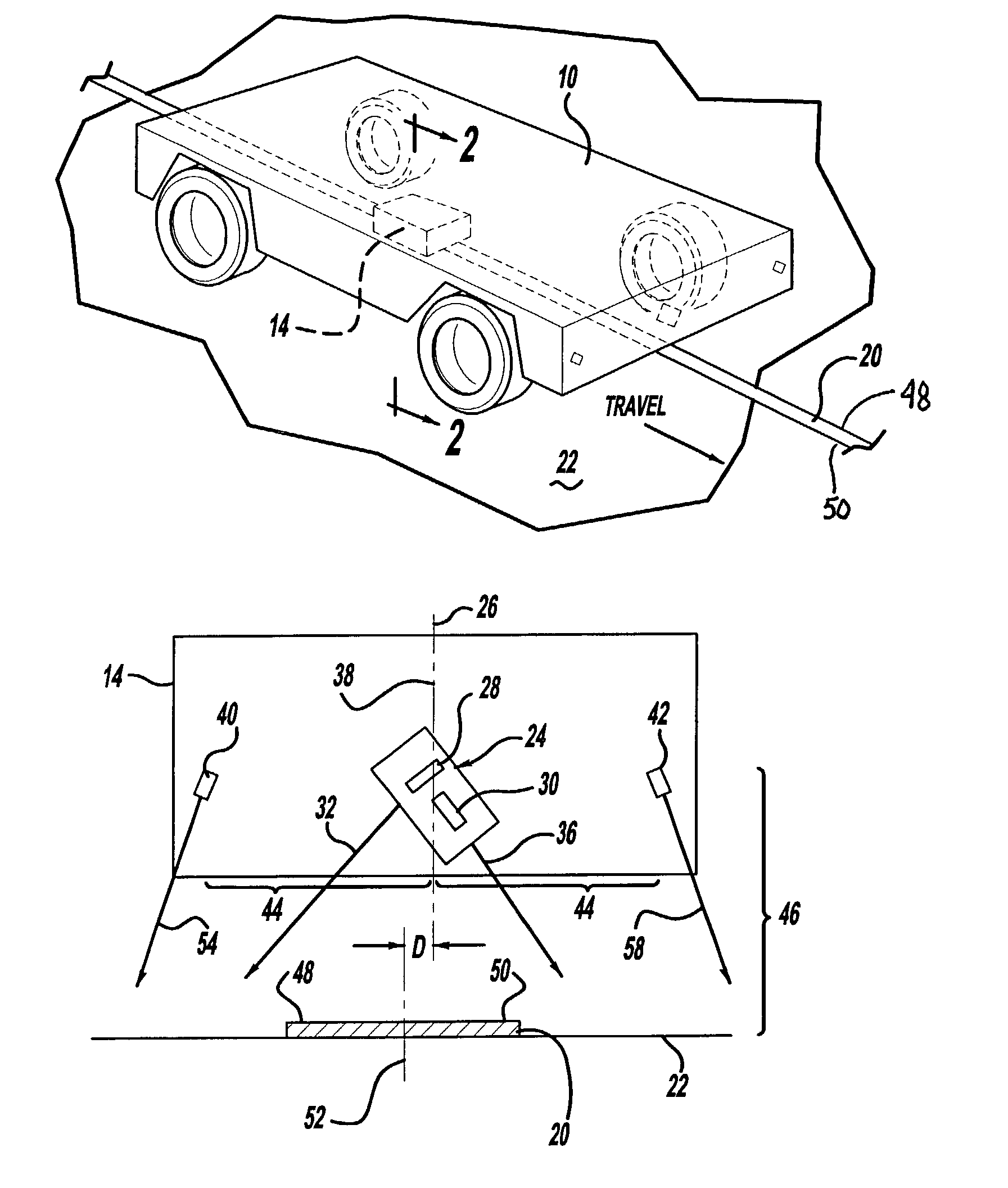
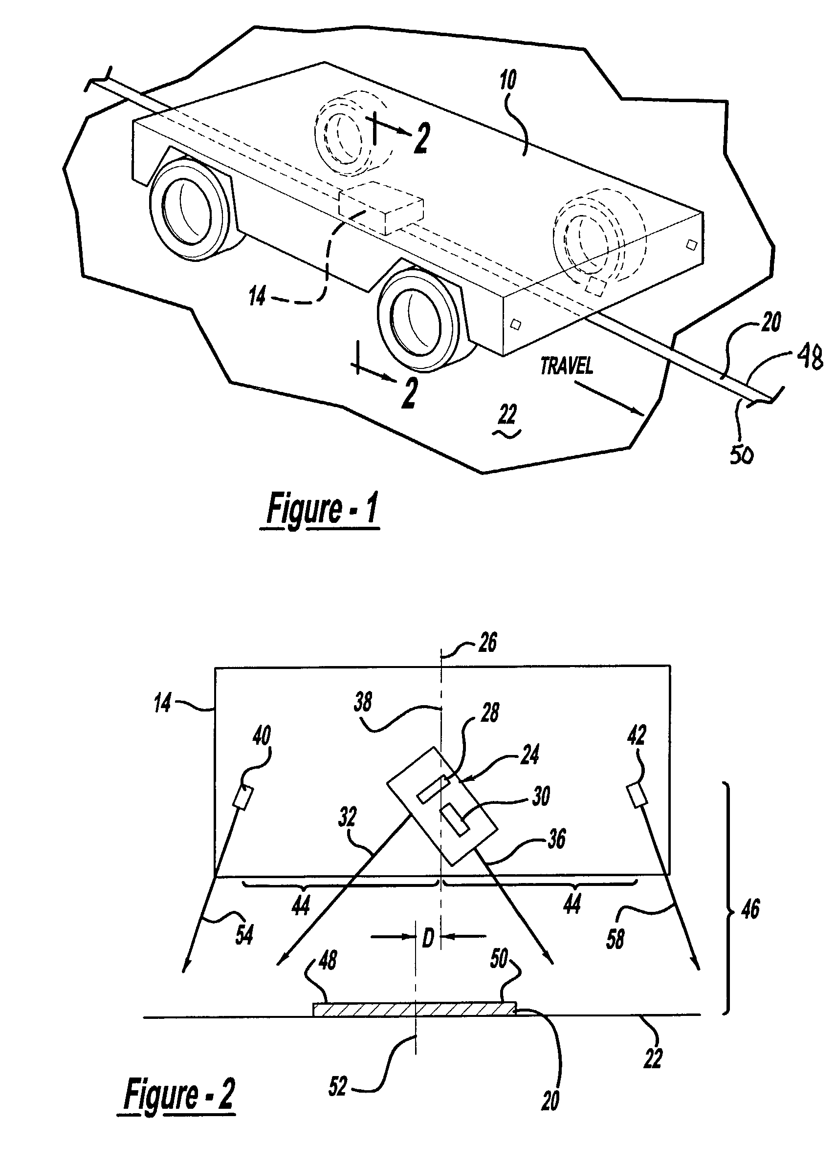
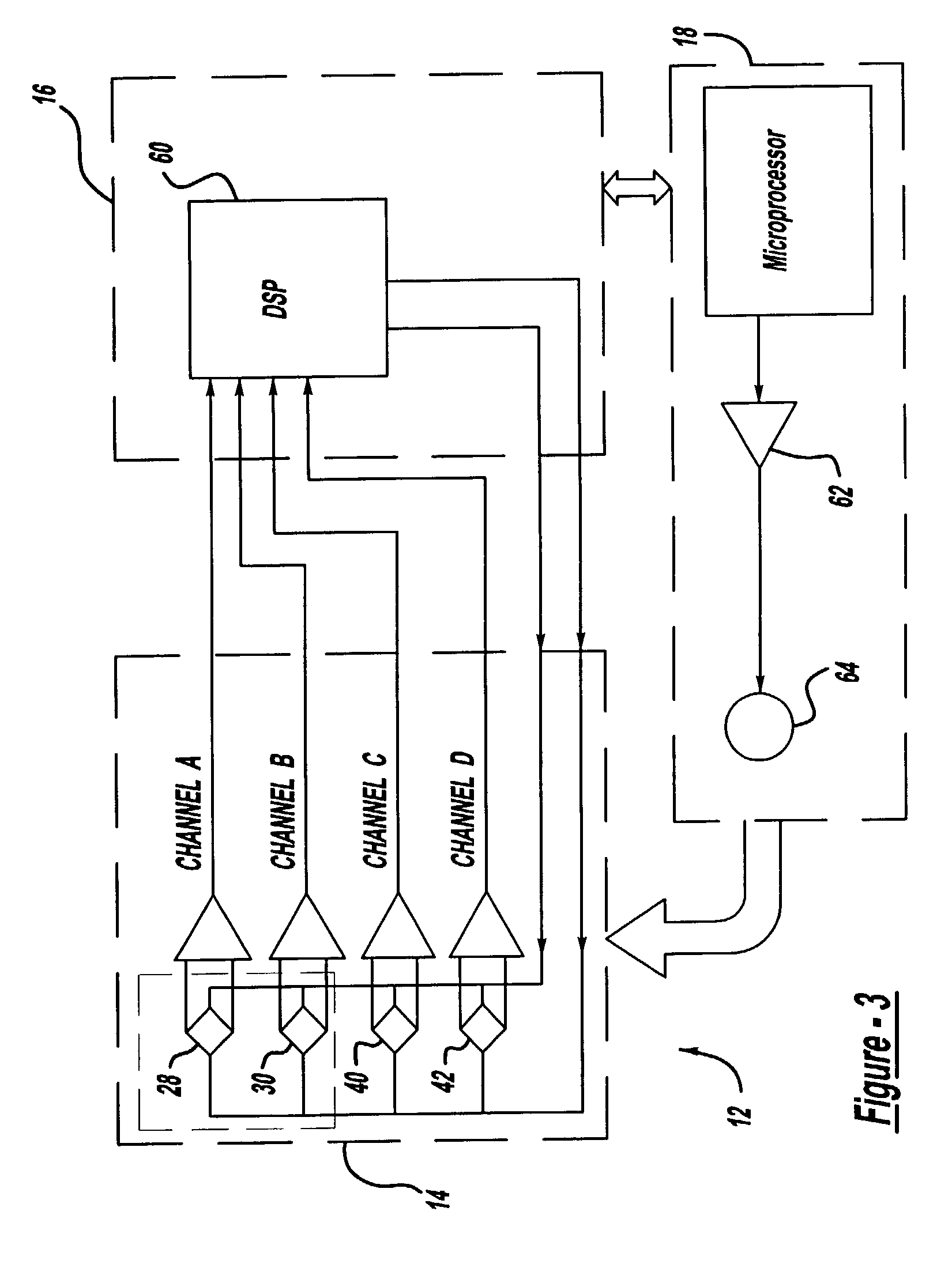
[0016]The present invention generally relates to a driverless vehicle including an improved guidance system for tracking a magnetically marked path. In the embodiment illustrated in the attached drawings, particularly FIGS. 1–3, the invention is shown to include a driverless vehicle 10 with a guidance system 12 having a sensor assembly 14, a signal processor 16, and a motion or steering controller 18. As is shown in FIG. 1, the vehicle 10 is configured to follow a magnetic guide path or marker 20 fixed to a floor 22. The guidance system 12, illustrated in FIG. 3, permits active tracking along the path or marker 20. More particularly, as is described in greater detail below, the signal processor 16 receives output signals from the sensor assembly 14 and determines an offset or lateral displacement of the vehicle 10 from the path or marker 20. The signal processor 16 communicates steering control information to the motion controller 18 which then adjusts the movement of the vehicle 10...


PUM


Abstract

A vehicle guidance system for guiding a vehicle along a magnetic marker including a first magnetic sensor having a sensing axis, the first sensor measuring a first magnetic field. A second magnetic sensor has a sensing axis, the second sensor measuring a second magnetic field. The sensing axis of the second magnetic sensor crosses the sensing axis of the first magnetic sensor at a vehicle guide point. A processor is configured to receive data representative of the magnetic field measured by the first and second sensors and to calculate a lateral offset between the guide point and the magnetic marker based upon the measured magnetic fields. A method for guiding a vehicle in response to a marker having magnetic field is also disclosed. The steps of the method include measuring magnetic field strength proximate the marker, measuring ambient magnetic field strength remote from the marker, nulling the ambient magnetic field by removing the remote magnetic field strength from the proximate magnetic field strength, calculating a lateral displacement between the vehicle and the marker using the nulled magnetic field strength, and guiding the vehicle in response to the lateral displacement between the vehicle and the marker.

Description

CROSS-REFERENCE TO RELATED APPLICATION[0001]This application claims the benefit of U.S. Provisional Application No. 60 / 341,195, filed Dec. 12, 2001, the entire disclosure of the application is considered part of the disclosure of this application and is hereby incorporated by reference.BACKGROUND OF THE INVENTION[0002]The present invention is directed to an apparatus and method for guiding a driverless vehicle along a path defined by a magnetic marker such as, for example, a strip of magnetic tape, magnetic paint, or bonded magnetic powder.[0003]Driverless vehicles with automated guidance systems have become increasingly commonplace in industrial applications. These vehicles are used to transport material along predetermined guide paths within a facility. Various methods of guiding the vehicle, such as dead reckoning, electrified guide wires, optical or magnetic markers, and inertial systems, are readily available in the art. However, each of these systems has drawbacks related, for...

Claims


Application Information

Patent Timeline
Patent Type & Authority Patents(United States)
IPC IPC(8): B60T7/16B62D1/28G05D1/02
CPCB60T7/16B62D1/28B62D1/283G05D1/0263G05D2201/0216
Inventor MARINO, MARKHONEY, DECEASED, ELVIN K.LEWIS, LEGAL REPRESENTATIVE, GEORGE
Owner JERVIS B WEBB INT CO
Why Eureka
Try Eureka