Combustion-operated setting device

a setting device and combustion-operated technology, which is applied in the direction of manufacturing tools, stapling tools, nailing tools, etc., can solve the problems of preventing the piston from returning to its starting position and unable to operate quickly, and achieve the effect of simple construction of the locking and unlocking mechanism

Active Publication Date: 2005-12-06
HILTI AG
View PDF7 Cites 22 Cited by
  • Summary
  • Abstract
  • Description
  • Claims
  • Application Information

AI Technical Summary

Benefits of technology

[0012]It is further advantageous when the locking device is constructed as a springing-elastic clip which is fastened at one of its ends to a structural component part of the setting device and is provided at its other, free end with a lock member which engages in a counter-lock in the locked position of the locking and unlocking mechanism to lock the combustion chamber outlet. The lock member and locking device are pretensioned or biased in a direction of the unlocked position by spring force, which acts counter to the magnetic attractive force of the magnet for the driving piston. A very simple, low-wear construction of the locking and unlocking mechanism can be achieved through this step.
[0013]When the combustion chamber outlet is constructed such that the combustion chamber wall can be lifted from the floor of the combustion chamber in the setting direction, a very simple construction of the locking and unlocking mechanism can be achieved such that one end of the locking device or clip is fastened to an end of the piston guide facing the combustion chamber and the counter-lock is arranged on the inside at the combustion chamber wall. By this step, a displacement of the combustion chamber wall relative to the piston guide can be prevented in the locked position of the device, while a displacement of the combustion chamber wall in the setting direction and, therefore, an opening of the combustion chamber outlet is possible when the locking device and lock member are swiveled out of the counter-lock.
[0014]It is also advantageous when the locking and unlocking mechanism is provided with means for compulsory unlocking by which the locking and unlocking mechanism can be moved manually into the unlocked position in case of an incorrect position of the piston.
[0015]This step is advantageous in that it is possible to vent the combustion chamber even when the incorrect position of the piston cannot be overcome directly.
[0016]In an advantageous construction for compulsory unlocking, the latter is carried out in that the combustion chamber wall is at least partly rotatable around the setting axis of the setting device. Due to the partial rotation of the combustion chamber wall around the setting axis, the lock member can be moved manually out of its position in which it engages behind the counter-lock arranged at the combustion chamber wall. In this way, compulsory unlocking is provided in a very simple manner.

Problems solved by technology

However, this is disadvantageous in that the piston feeler rubs against the piston rod during the return of the piston and accordingly impedes the return of the piston to its starting position.
However, this solution is disadvantageous in that rapid operation is impossible because after every setting process it is necessary to wait until the delay time of the trigger switch expires before another setting process can be carried out.

Method used


Image

  • Combustion-operated setting device
  • Combustion-operated setting device
  • Combustion-operated setting device

Examples


Embodiment Construction

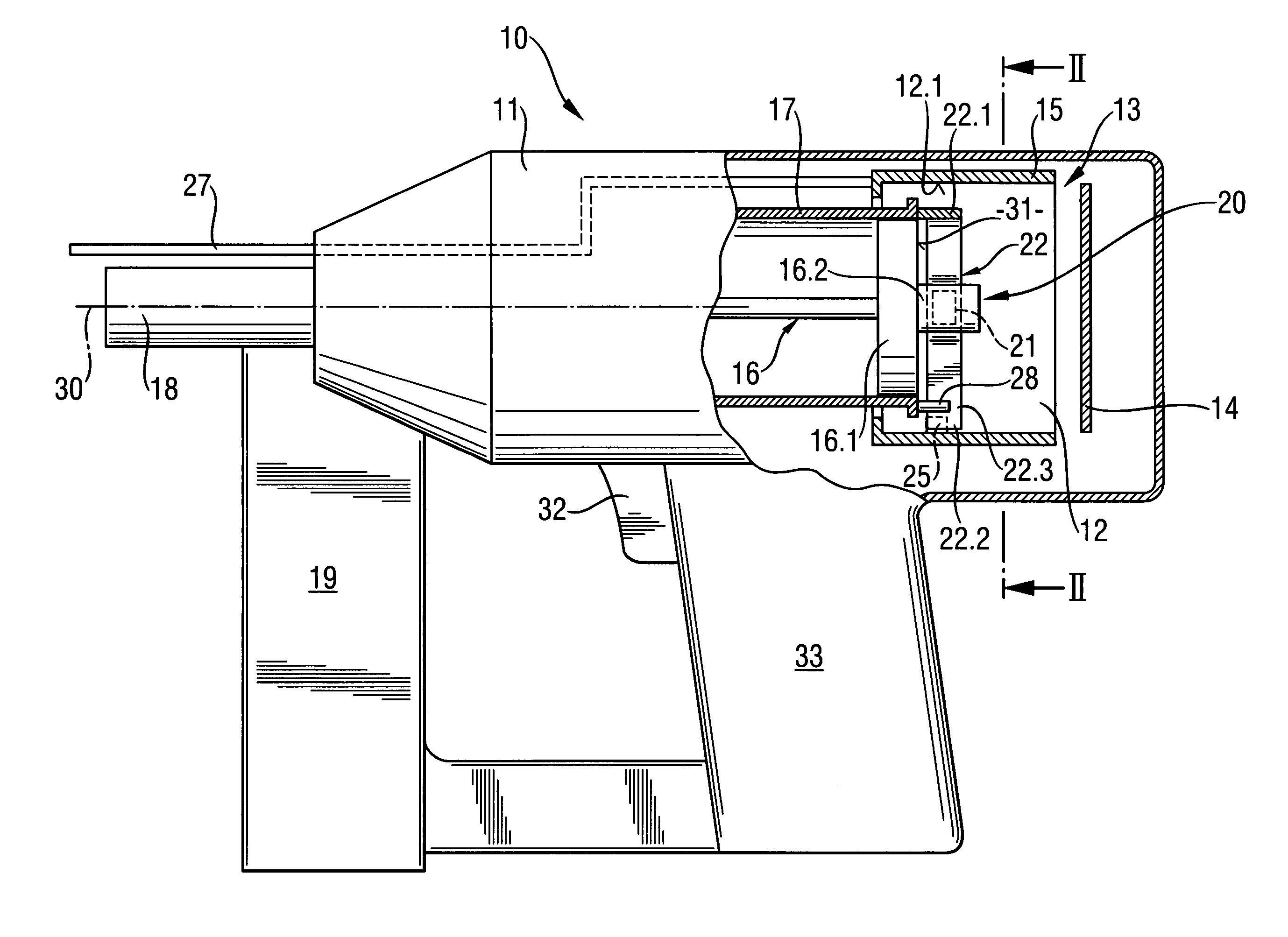
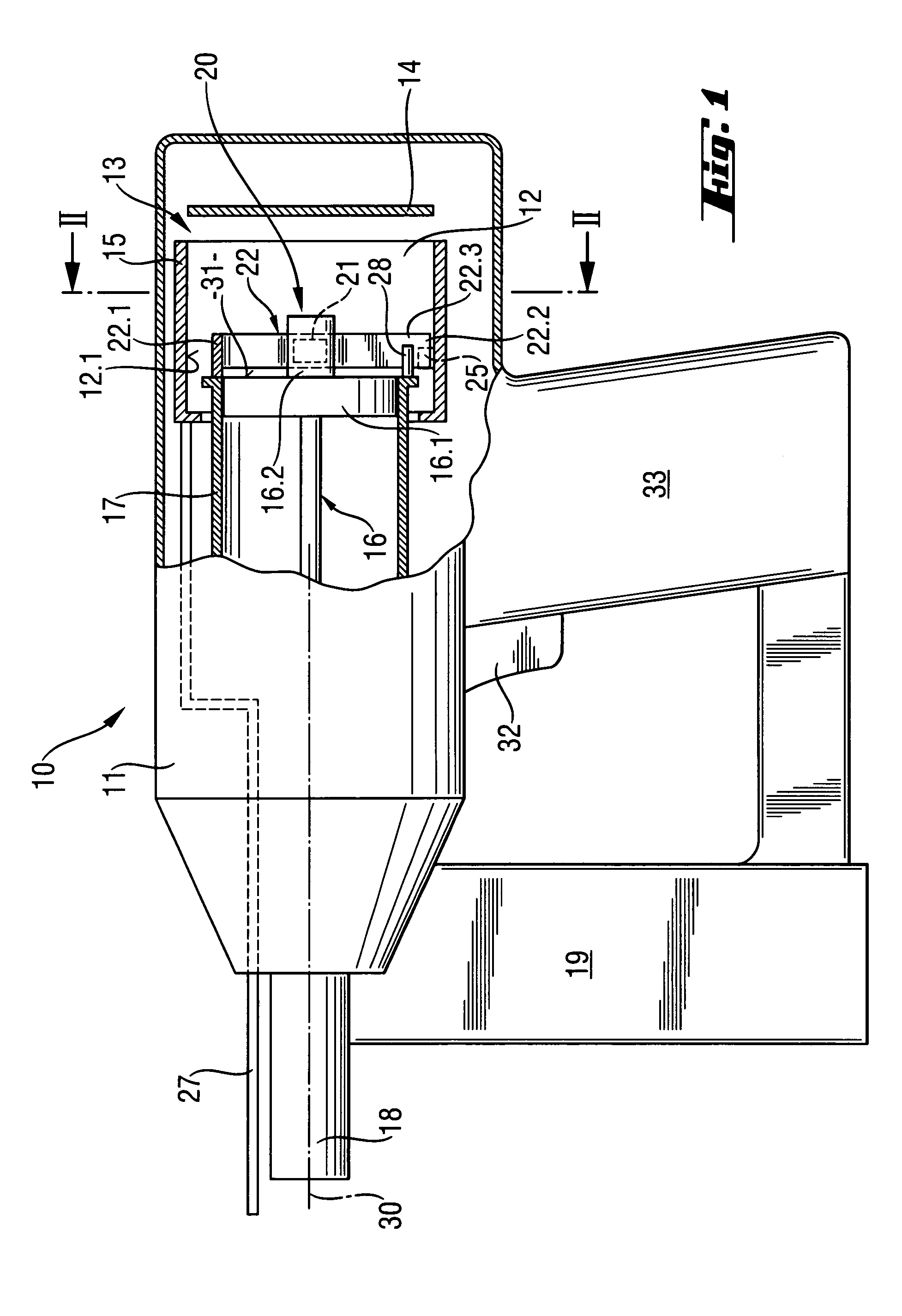
[0023]The setting device 10 according to the invention is shown in its starting or rest position in FIGS. 1 and 2. In the present embodiment example, the setting device 10 is operated by a fuel gas which is stored in a fuel gas vessel, not shown, at the setting device. The setting device 10 has a housing 11 in which a setting mechanism is arranged for driving fastening elements into a substrate. The setting mechanism includes a combustion space or combustion chamber 12, a piston guide 17 in which a driving piston 16 is displaceably mounted, and a pin guide 18 for guiding a fastening element. Fastening elements can be stored in a magazine 19 at the setting device 10.

[0024]In the present embodiment, an ignition unit (not shown in the drawing) is also provided in the combustion chamber 12 for igniting an air / fuel gas mixture introduced into the combustion chamber 12 for a setting process. A switching device, e.g., a trigger switch 32, is provided at a handle 33 of the setting device 10...


PUM

PropertyMeasurementUnit
spring forceaaaaaaaaaa
combustion pressureaaaaaaaaaa
pressureaaaaaaaaaa

Abstract

The present invention is directed to a combustion-operated setting device for driving fastening elements such as nails, bolts and pins into a substrate, with a combustion chamber (12) that has at least one combustion chamber outlet (13) in which a fuel gas mixture can be ignited for driving a driving piston (16) guided in a piston guide (17), and with a locking and unlocking mechanism (20) for unlocking the at least one combustion chamber outlet (13) in the starting position (31) of the driving piston (16) and for locking the at least one combustion chamber outlet (13) outside of the starting position (31) of the driving piston (16). The locking and unlocking mechanism (20) has a magnet (21) for detecting the driving piston (16) in the starting position (31).

Description

BACKGROUND OF THE INVENTION[0001]The present invention is directed to a combustion-operated setting device for driving fastening elements into a substrate, with a combustion chamber which has at least one combustion chamber outlet and in which a fuel gas mixture can be ignited for driving a driving piston guided in a piston guide, and with a locking and unlocking mechanism for unlocking the at least one combustion chamber outlet in the starting position of the driving piston and for locking the at least one combustion chamber outlet outside of the starting position of the driving piston. Setting devices of this kind can be operated by gaseous or liquid fuels that are burned in a combustion chamber and drive a driving piston for fastening elements.[0002]In fuel-operated setting devices, e.g., with liquid-gas driving means, the piston is guided back to its initial or starting position at the combustion chamber after the ignition of the air-fuel mixture in the combustion chamber and th...

Claims


Application Information

Patent Timeline
Patent Type & Authority Patents(United States)
IPC IPC(8): B25C1/08
CPCB25C1/08
Inventor SCHIESTL, ULRICHROSENBAUM, ULRICHWOLF, IWANGSCHWEND, HANSHERTLEIN, PETER
Owner HILTI AG
Why Eureka
Try Eureka