Vehicle bumper beam

a technology for bumper beams and vehicles, applied in the direction of bumpers, vehicle components, vehicular safety arrangments, etc., can solve the problems of kinks, affecting the shape of the beam, and becoming more and more difficult to form raw sheet stock into the desired beam shape, etc., to achieve optimally high strength-to-weight ratios, increase cost, and ultra-high strength

Active Publication Date: 2005-12-06
SHAPE CORP
View PDF49 Cites 81 Cited by
  • Summary
  • Abstract
  • Description
  • Claims
  • Application Information

AI Technical Summary

Benefits of technology

[0012]An object of the present invention is to provide a design that accommodates complexity without a concurrent increase in cost due to the need for substantial secondary processing.
[0019]The present invention overcomes the drawbacks of roll-formed sections having a constant cross section, by providing for an optimized utilization of geometry and material to produce a bumper beam that possesses the strength and rigidity characteristics of a tubular bumper section. The present invention combines manufacturing processes and material to produce a tubular section that has varying cross-sectional geometries along a length of the part and different material properties around the cross section of the part. The present invention differs from prior art that includes the addition of material to specific areas to provide localized stiffening.

Problems solved by technology

In contrast, open sections tend to prematurely buckle during impact since the “legs” of the open sections will spread apart, kink, and quickly lose shape upon impact.
However as higher and higher-strength materials are used, it becomes more and more difficult to form raw sheet stock into the desired beam shape, because the higher-strength materials are harder and harder on tooling and the presses that run them.
Roll-forming processes have the ability to form higher-strength materials than stamping processes, however roll-forming processes are limited to producing a constant cross-sectional shape along a length of the roll-formed parts.
However, as noted above, a drawback to roll-forming is that the roll-forming process can only produce a constant cross section over the entire length of the part.
Regarding the constant cross section produced by roll-forming, this often does not satisfy current styling trends which require variations in cross-sectional size along a length of the beam due to packaging space over the vehicle frame rails (versus the packaging space available at a centerline of the vehicle), or which require a longitudinal sweep with an increased curvature at corners of the vehicle (e.g. at the fenders).
But these secondary processes are expensive because end-forming and / or taper cutting the parts is not easy (particularly when they are made of high-strength materials).
Alternatively, the ends of tubular sections may be reformed to better fit functional and aesthetic styling concerns (see Sturrus U.S. Pat. No. 5,306,058), but it is difficult to accurately and consistently deform the ends, thus potentially leading to unacceptable dimensional variations and high tooling wearout.
Beams made from C-shaped open sections can be formed to a desired three-dimensional shape, including non-uniform cross sections along their length, but their open section is inherently not as strong as a tubular shape during an impact.
Specifically, the open sections include rearwardly-extending legs that tend to prematurely spread apart or otherwise collapse upon impact.
This greatly reduces the beam's overall sectional impact strength and reduces its ability to consistently and predictably absorb energy.
However, these additional reinforcements require expensive secondary operations since they utilize considerable fixturing and welding machinery, and they often require several additional parts and considerable assembly time and in-process inventory.
Also, the process of welding multiple reinforcements to an open beam can be difficult to control, since multiple parts must be carefully separately fixtured and each and every one of the parts welded very consistently in place.
Also, the location of each stabilizing strap can greatly affect impact strengths along the beam.
To summarize, packaging and performance requirements of bumper beams on vehicles and related vehicle front end (or rear end) components often increase the complexity of a bumper design since they result in the addition of other structural components, which might include bridges, bulkheads, radiator supports, fascia supports, fascia, and the like.
This increase in complexity results in an increase in cost due to substantial secondary processing.
It also results in difficult tradeoffs between function and styling criteria.
An additional problem is that ultra-high-strength materials are difficult to form in stamping presses, or at least it is preferable not to do so.
Specifically, those skilled in the art prefer not to stamp materials such as ultra-high-strength steels (UHSS) because the UHSS material is so strong that it is hard to form without cracking and that it damages or quickly wears out the stamping dies and the stamping press.

Method used


Image

  • Vehicle bumper beam
  • Vehicle bumper beam
  • Vehicle bumper beam

Examples


Embodiment Construction

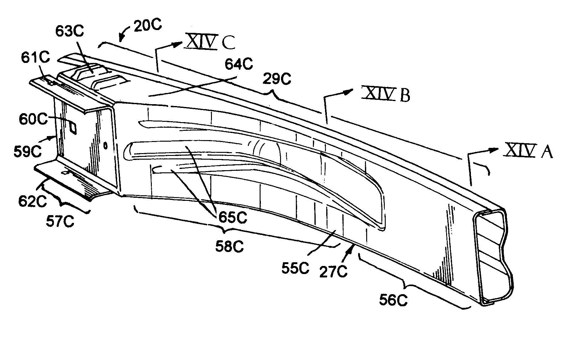
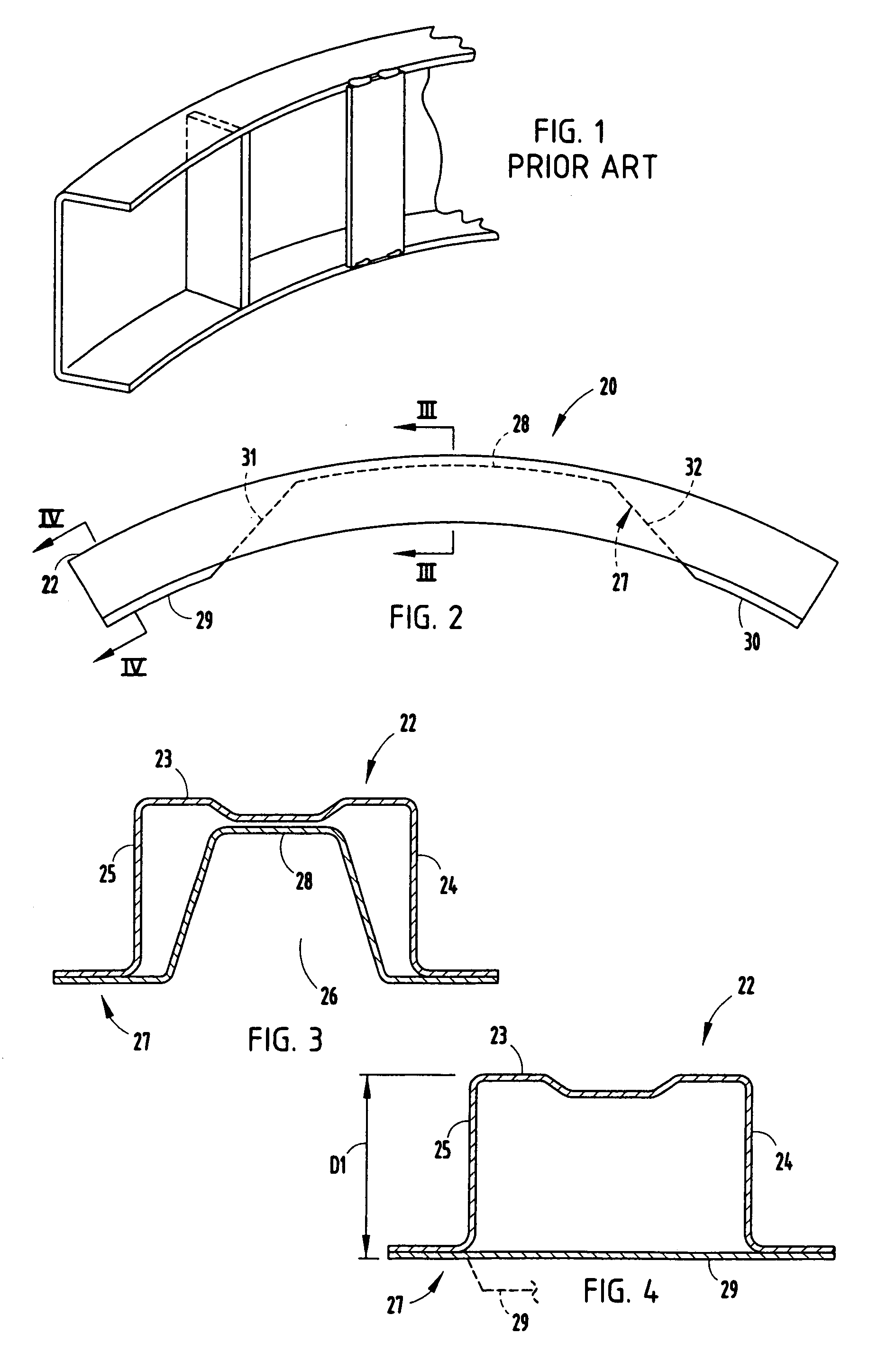
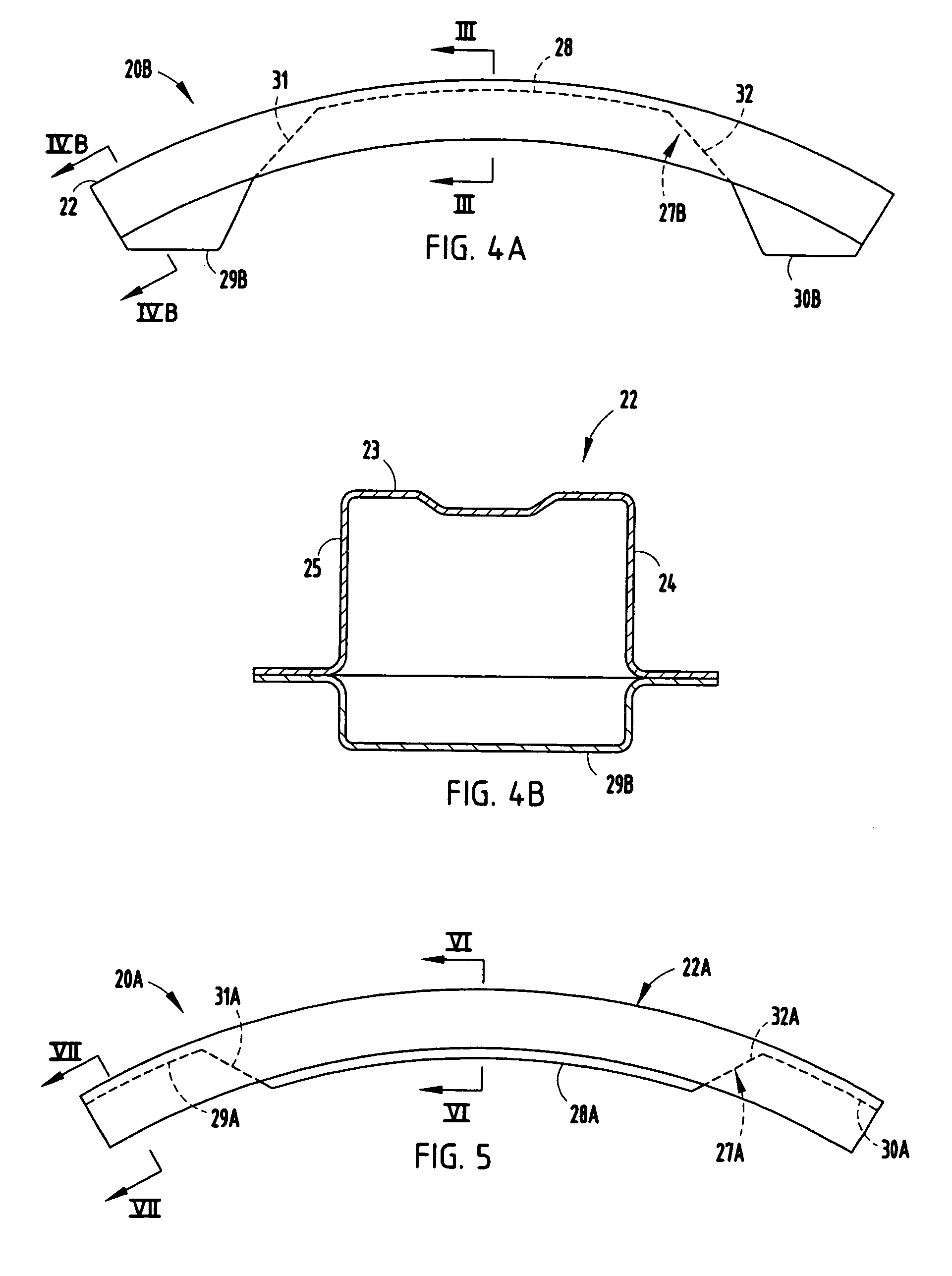
[0033]The present invention focuses on a bumper beam 20 (FIG. 2) (and beam 20A, FIG. 5; and beam 20B, FIG. 4A) utilizing a roll-formed front section (22, 22A) (also called a “front channel” or “rolled section”) and a stamped or molded back section (27, 27A, 27B) (also called a rear channel” or “reinforcement section”) mated together to form a beam of varied tubular cross-sectional shape. More specifically, the present invention represents a two-piece solution that when combined produces a tubular bumper beam with varying cross section across the length of the bumper and material properties that change around the cross section. The ability to change cross section across bumper length allows for optimization of impact beam performance, weight, and cost along any selected region of the beam. For example, the use of ultra-high-strength steels (UHSS steels) provides desirable characteristics for impact beam construction. The high mechanical properties inherent to UHSS steels support impa...


PUM


Abstract

A bumper beam includes an open front section made from a high-strength material such as ultra-high-strength steel (UHSS) material, and further includes a mating back section made of lower-strength material attached to a rear side of the front section along abutting flanges. The front and back sections combine to define different tubular cross sections. The front section can be roll-formed, and the back section can be stamped, thus taking advantage of roll-forming processes' ability to form high-strength materials, while allowing the back section to have a more complicated shape and be stamped. The abutting flanges telescopingly overlap in a fore-aft direction of the vehicle and are welded together at locations that potentially experience shear upon impact, but the flanges of the front section are captured within the flanges of the backs section, thus providing impact strength even if the attachment locations shear off.

Description

[0001]This is a continuation-in-part of co-assigned application Ser. No. 10 / 877,326, filed Jun. 25, 2004, entitled VEHICLE BUMPER BEAM, the entire contents of which are incorporated herein in their entirety.BACKGROUND[0002]The present invention relates to vehicle bumper beams, and more particularly relates to a bumper beam having a front section of continuous shape and a back section attached to the front section to make a tubular beam of changing cross-sectional size.[0003]Two basic types of bumper beams often used on modern vehicles are tubular sections (also called closed sections, such as “B” or “D” shapes) and open sections (such as “C” sections or “hat” sections). The tubular sections and also the open sections each have their own advantages and disadvantages. For example, from an engineering standpoint, bumper beams made from tubular sections are inherently more rigid and capable of absorbing and / or transmitting more energy (especially based on a strength-to-weight ratio) on ...

Claims


Application Information

Patent Timeline
Patent Type & Authority Patents(United States)
IPC IPC(8): B60R19/02B60R19/04B60R19/18
CPCB60R19/18B60R2019/1813B60R2019/1826B60R19/24
Inventor HEATHERINGTON, DAVID W.GLASGOW, SCOTT C.LYONS, BRUCE W.
Owner SHAPE CORP
Why Eureka
Try Eureka