
Sensor readout circuit

a technology of readout circuit and sensor, which is applied in the direction of frequency to phase shift conversion, resonant frequency, instruments, etc., can solve the problems of difficult to read out additional sensor characteristics, complicated readout of these sensors, and limit the rate of updating the readout of the sensor, so as to facilitate the determination of the resonant q of the sensor, the effect of being inexpensive and compact in design

Inactive Publication Date: 2005-12-06
CHARLES STARK DRAPER LABORATORY
View PDF12 Cites 12 Cited by
  • Summary
  • Abstract
  • Description
  • Claims
  • Application Information

AI Technical Summary

Benefits of technology

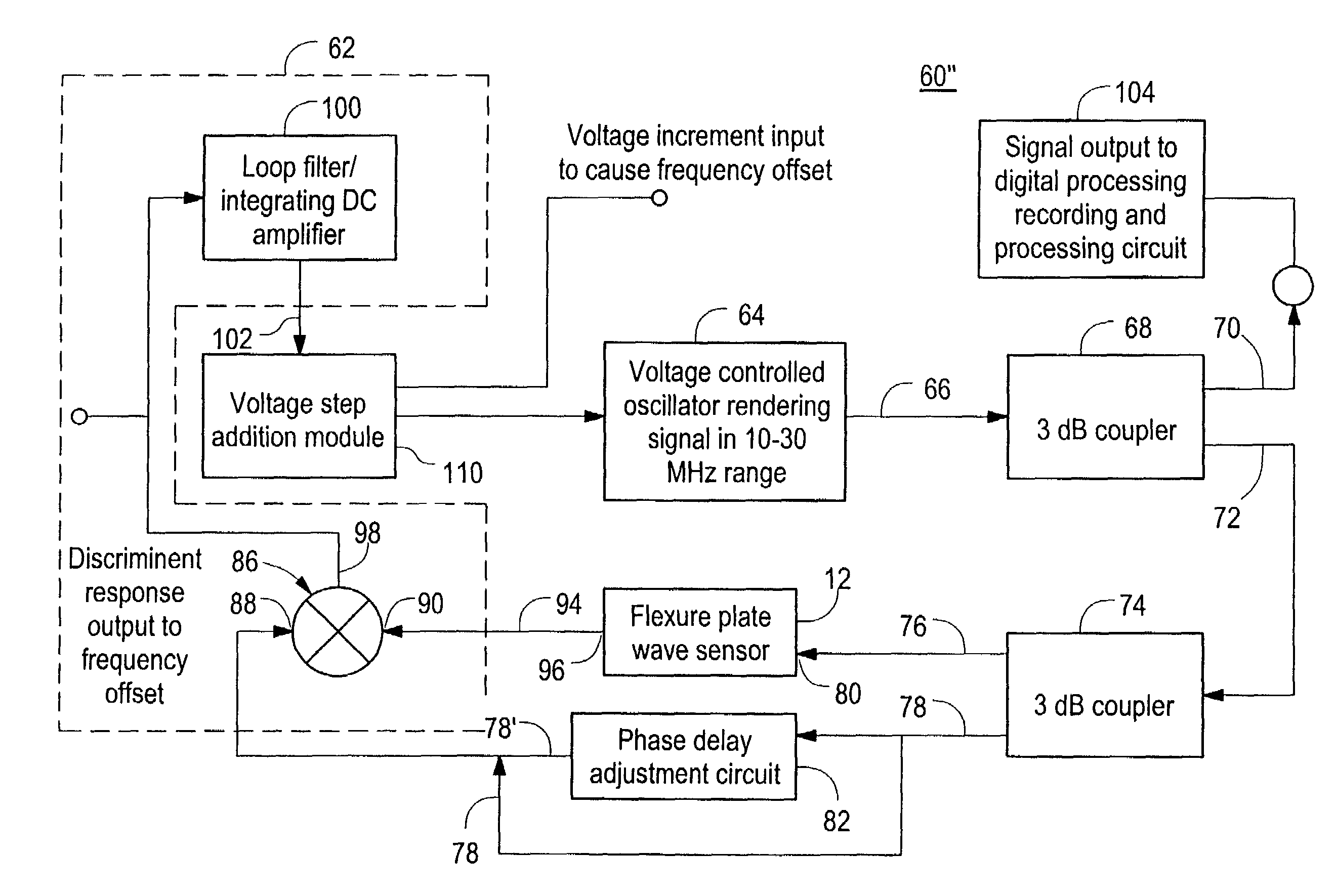
[0008]It is a further object of this invention to provide a sensor readout circuit which eliminates the need to sweep the frequency response of a sensor to determine the resonant frequency of a sensor.
[0009]It is a further object of this invention to provide a sensor readout circuit which can isolate specific resonance frequencies when multiple resonant frequencies are present.
[0010]It is a further object of this invention to provide a sensor readout circuit which can easily determine the resonant Q of a sensor.
[0011]It is a further object of this invention to provide a sensor readout circuit which is inexpensive and compact in design.

Problems solved by technology

Readout of these sensors is complicated by the fact that multiple resonant peaks may be present in a typical response of the sensor.
However, this prior art technique has several disadvantages.
Sweeping the frequency response of the sensor requires complex and expensive electronics which require substantial signal processing which can limit the rate of updating the sensor readout.
Further, it is difficult to read out additional sensor characteristics, such as multiple resonant frequencies and resonant Q's associated with these resonances.

Method used


Image

  • Sensor readout circuit
  • Sensor readout circuit
  • Sensor readout circuit

Examples


Embodiment Construction

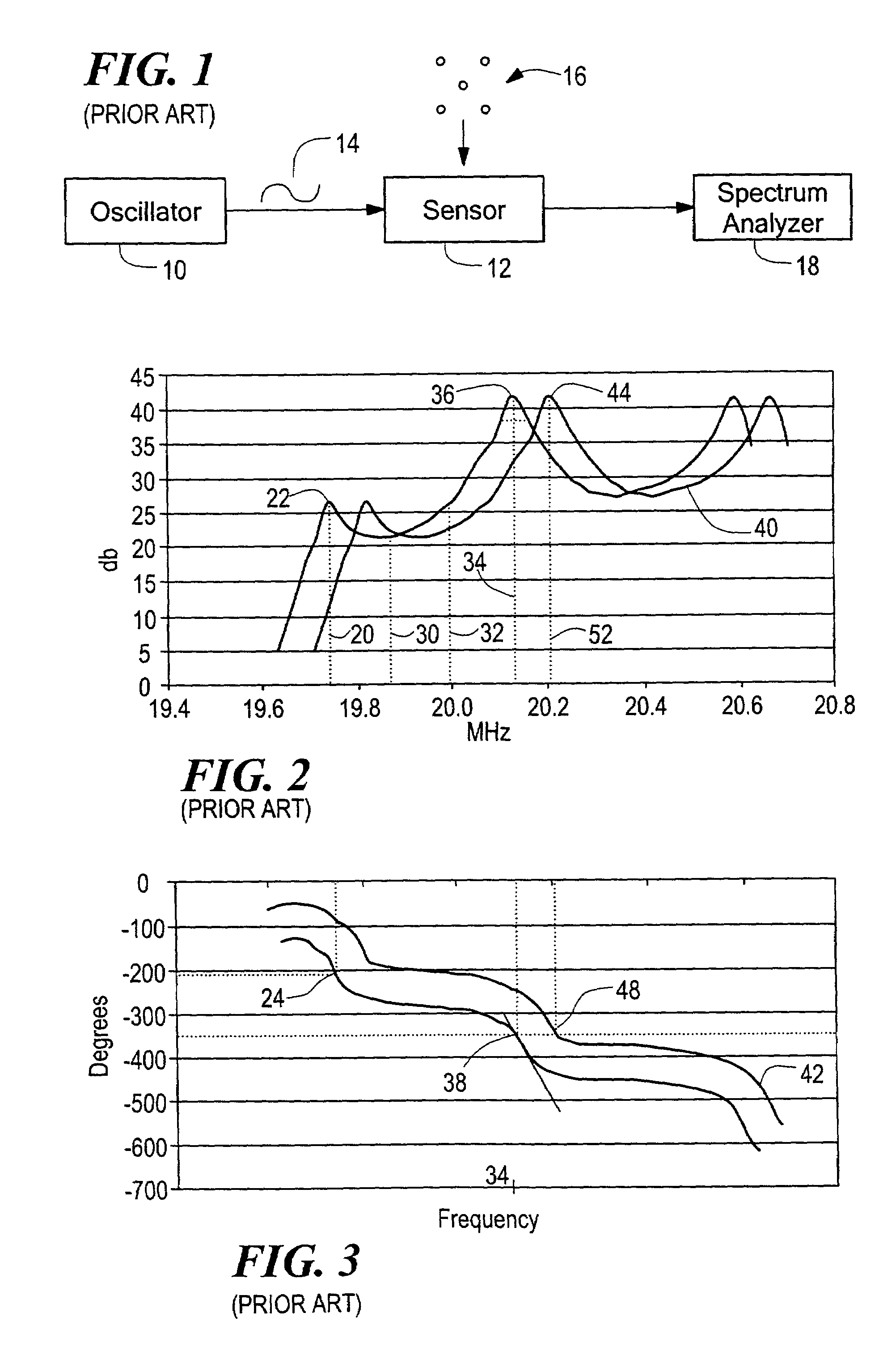
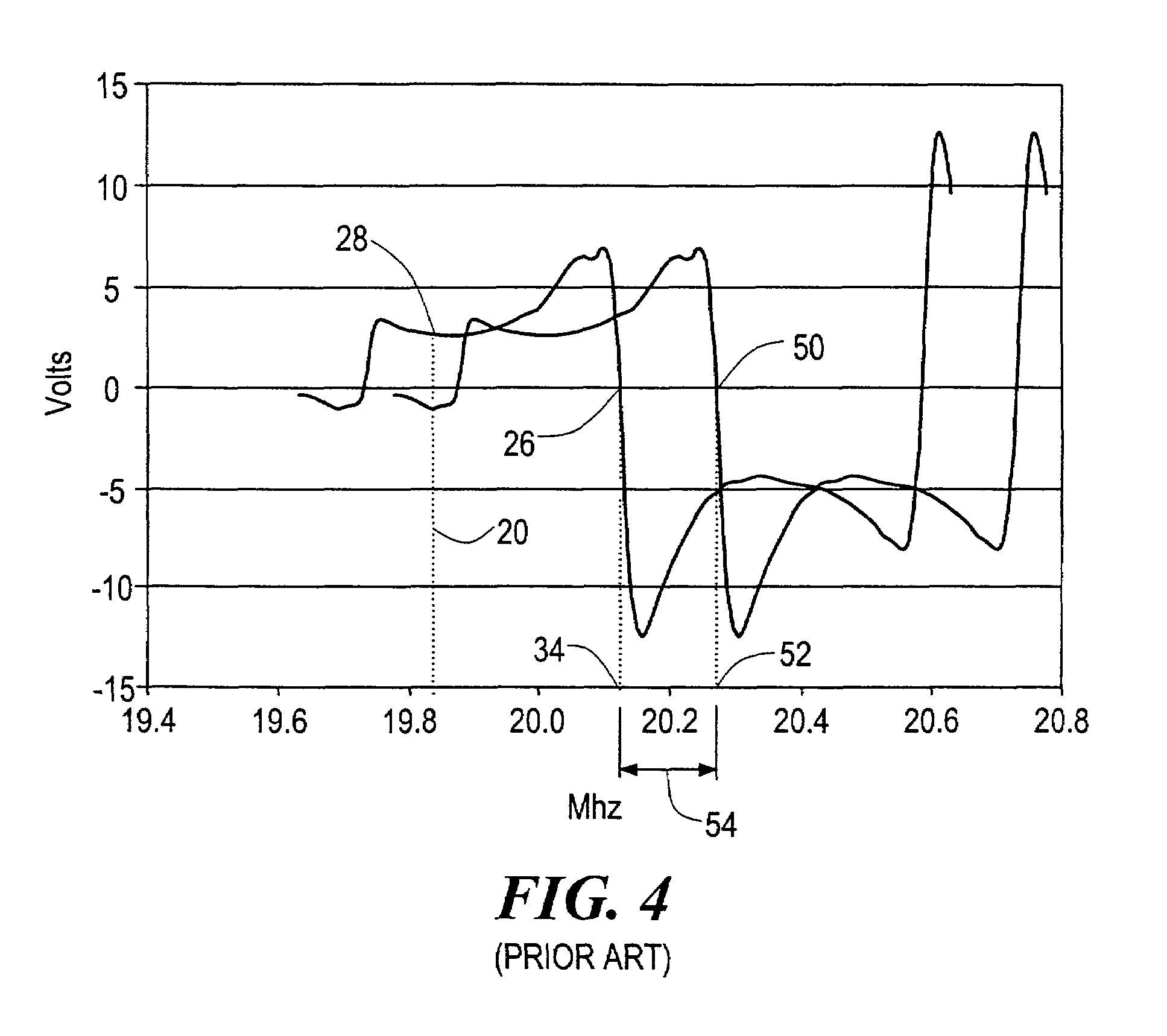
[0026]As discussed in the Background of the Invention above, one prior art technique for reading out the resonant frequency response of a sensitive mass sensor includes the use of a swept frequency response measurement. Using this technique, a frequency is chosen, the magnitude and phase angle of the response is measured, and a calculation is performed to determine if the resonant peak of the sensor is at the chosen frequency. The process is repeated until the frequency of the resonant peak of the sensor is found. The resonant frequency of the sensor, in turn, provides a measurement of any mass loading to the sensor.

[0027]The prior art swept frequency response measurement technique employs oscillator 10, FIG. 1, to drive sensor 12, such as a flexure plate wave resonator, with sinusoidal voltage 14. Spectrum / network analyzer 18 measures the magnitude of voltage amplitude 22, FIG. 2, of the response of sensor 12 to sinusoidal voltage 14, FIG. 1 at a chosen frequency 20. Phase angle 24...


PUM

PropertyMeasurementUnit
frequencyaaaaaaaaaa
frequencyaaaaaaaaaa
phaseaaaaaaaaaa

Abstract

A sensor readout circuit which provides a frequency signal output including a phase detector circuit responsive to an output signal from a sensor and an input signal to the sensor and configured to detect the phase difference between the input signal and the output signal, and a drive circuit responsive to the phase detector circuit and configured to maintain a fixed phase difference between the input signal and the output signal.

Description

FIELD OF THE INVENTION[0001]This invention relates to a sensor readout circuit and more particularly to a sensor readout circuit which continuously outputs the resonance frequency of the sensor.BACKGROUND OF THE INVENTION[0002]The sensitivity of chemical and gravimetric sensors employing mass sensors, such as flexure plate wave resonators, is based on the sensitivity of the mass sensor velocity and resonant frequency to mass loading of the sensor. Many applications require that the resonant frequency of the sensor response be measured continuously to provide a measurement of any mass loading to the sensor. Readout of these sensors is complicated by the fact that multiple resonant peaks may be present in a typical response of the sensor.[0003]In the prior art, one method for reading out the resonant frequency of a sensor is a swept frequency response measurement. The swept frequency response measurement technique relies on sweeping the frequency response of the sensor with a spectrum...

Claims


Application Information

Patent Timeline
Patent Type & Authority Patents(United States)
IPC IPC(8): G01D3/06G01H13/00G01N27/00
CPCG01D3/06G01H13/00G01N29/036G01N2291/0256
Inventor PETROVICH, ANTHONYWILLIAMS, JOHN R.DUBE, CHRISTOPHER E.
Owner CHARLES STARK DRAPER LABORATORY
Learn More