
Method for modem element switchover using multicast groups

a multicast group and modem technology, applied in the field of telecommunications, can solve the problems of information loss, inability to accept business, information loss, packet drop, etc., and achieve the effect of little or no loss

Inactive Publication Date: 2005-12-06
UTSTARCOM INC
View PDF24 Cites 22 Cited by
  • Summary
  • Abstract
  • Description
  • Claims
  • Application Information

AI Technical Summary

Benefits of technology

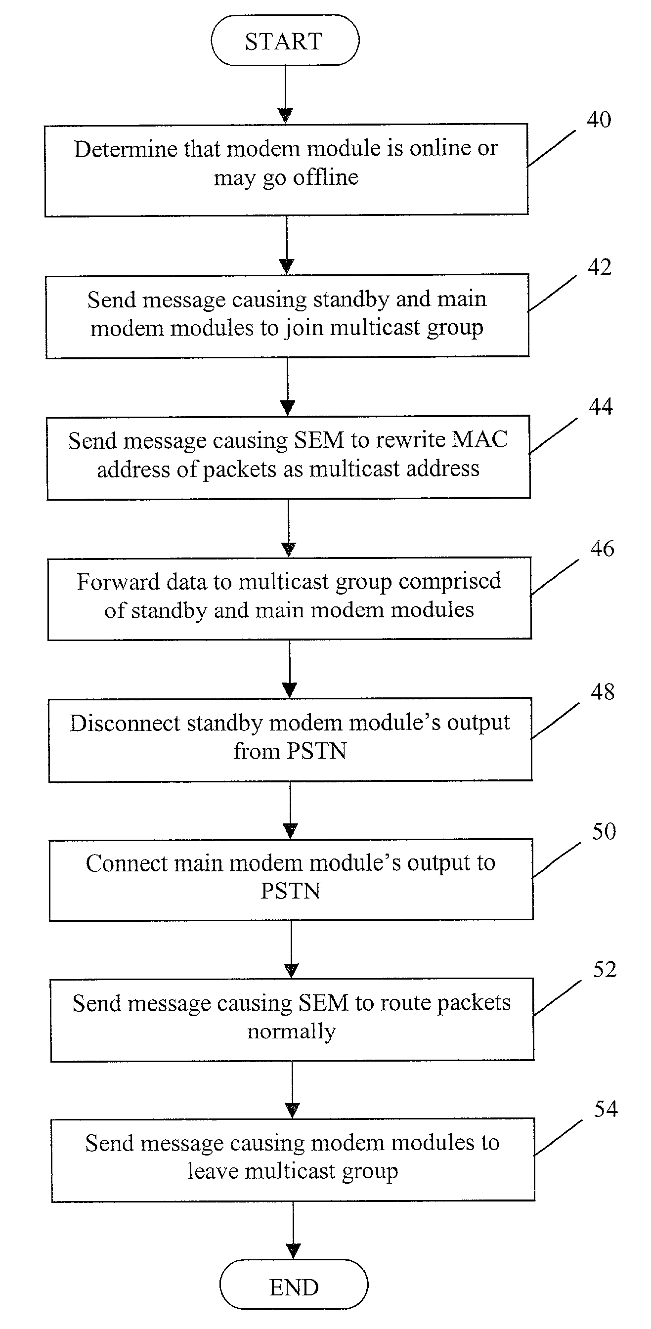
[0011]Once data are being sent simultaneously to both modem elements, the standby modem element can be disconnected from the PSTN. For example, an electromechanical relay or a solid-state relay may be used to physically disconnect the standby modem element's output from the PSTN. Alternatively, the “disconnecting” may be accomplished in software, where data to and from the PSTN are processed in parallel by both modem elements. If this method is used, switchover can be accomplished without any packet loss.
[0015]A sending component that sends the readdressed data to the at least one first network element and the at least one second network element via the second network may also be used. The sending component may also be software and associated hardware in the switch egress module that forwards packets to the modem elements via a network, such as an Ethernet network. A switching component that “disconnects” the standby modem element from the PSTN and “connects” the main modem element to the first PSTN may also be included in the system. The switching component may an electromechanical or a solid-state relay, or any other devices capable of connecting and disconnecting network elements. Alternatively the switching component may be a software implementation where data are made available to both the standby and main modem element but only processed by one module, so that a switchover may be made without any data loss.

Problems solved by technology

Today, however, many new applications are placing real-time demands on the Internet.
In addition to the timing of data arrival, lost information, in the form of dropped packets, is unacceptable to a business that wishes to provide its customers with Voice-over-IP (VoIP) or video-over-IP in competition with legacy suppliers of these services, such as local exchange carriers and cable television providers.
During the time between initial failure detection and switchover, information will be lost.
Similarly, when the failed element recovers or is replaced, switching it back into service (“revertive switchover”) may create a loss of information during the transition from the backup element.
However, such storing, copying, and forwarding of a copy of packets to all or multiple elements is not efficient, because a switch that stores, copies, and forwards packets will not be able to transfer data at wire speed.
Further, such storing copying, and forwarding consumes processing and memory resources.

Method used


Image

  • Method for modem element switchover using multicast groups
  • Method for modem element switchover using multicast groups
  • Method for modem element switchover using multicast groups

Examples


Embodiment Construction

1. Exemplary Architecture

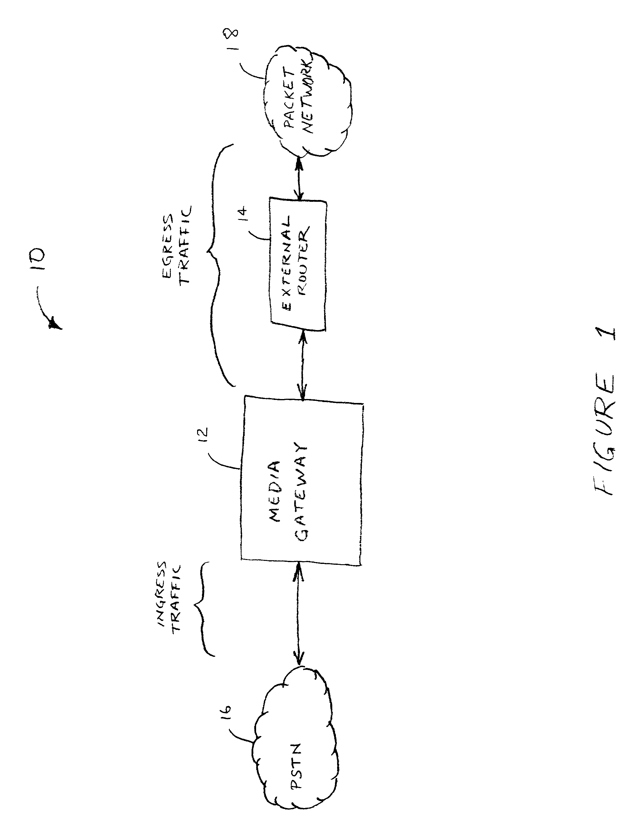
[0022]Referring to the drawings, FIG. 1 illustrates a simplified block diagram of a system 10 in which an exemplary embodiment of the present invention may be employed. Specifically, FIG. 1 is an illustration of a voice over IP (VoIP) system. As shown in FIG. 1, system 10 includes a media gateway 12 interconnected to a PSTN 16 and, via an optional external router 14, to a packet network 18. Media gateway 12 serves as an interface between the PSTN and IP network, and it may typically digitize, encode, and compress originating voice traffic (i.e., ingress traffic) into packets for transport over managed IP networks. Media gateway 12 may also decompress, decode, and reassemble terminating voice traffic (i.e., egress traffic) for handoff to PSTN 16 via the local carrier's network. Media gateway 12 is a functional more than a physical entity, although it may be a standalone (physical) device. Media gateway 12's functionality may be provided, for example, by one o...


PUM


Abstract

A method for switching between a first network element and a second network element, the first and second network elements each connected to a first network and a second network. The method may be carried out by configuring the first network element and the second network element to recognize the same data from the second network. Next, data may be readdressed so that it may be recognized by both network elements. After readdressed data are sent to the first network element and the second network element, the first network element may be disconnected from the first network and the second network element may be connected to the first network. Data may be forwarded from the second network to the first network with little or no loss during the switchover.

Description

BACKGROUND OF THE INVENTION[0001]1. Field of the Invention[0002]The present invention relates generally to telecommunications and, more particularly, to any IP telecommunication technology, such as Voice over IP (VoIP) services.[0003]2. Description of Related Art[0004]As technology has advanced, making very high-speed computer networks widely available, it has become possible to use the networks for more diverse applications. Initially, the Internet was designed to carry data that were digital in nature, such as text files. With such digital files, Internet data transfers were satisfactory as long as the full file reached its destination in a reasonable time. Today, however, many new applications are placing real-time demands on the Internet. For example, when voice, music, video and still images are transferred, the timing of data arrival becomes crucial (or at least much more important) to the network's usefulness in carrying the information.[0005]In addition to the timing of data...

Claims


Application Information

Patent Timeline
IPC IPC(8): G08C15/00H04L12/18H04L12/28H04L69/40
CPCH04L12/18H04L12/5692H04L69/40H04L69/14Y02B60/33Y02D30/50
Inventor JOSEPH, BOBYRADHAKRISHNAN, SAJIPUTHIYANDYIL, SANIL KUMARRAMANKUTTY, RAJESH
Owner UTSTARCOM INC
Learn More