Self priming regenerative pump

a regenerative pump and self-priming technology, applied in the field of self-priming regenerative pumps, can solve the problems of affecting the pump function, affecting the pump unit size, and difficult maintenance, such as cleaning and disinfection, and achieve the effect of reducing the flow speed and pressure and increasing the buoyancy

Active Publication Date: 2005-12-13
NIKKISO COMPANY
View PDF8 Cites 17 Cited by
  • Summary
  • Abstract
  • Description
  • Claims
  • Application Information

AI Technical Summary

Benefits of technology

[0010]With such a constitution, the liquid flows through both the communicating passage and the small diameter part and is discharged from the discharge port during the normal operation, while the liquid flows only through the small diameter part and the liquid returns through the communication passage to the pressurizing passage when a lot of gasses is mixed in the liquid. The liquid, after passing through the small diameter part, reduces its flow speed and pressure, so that smaller bubbles unite, increasing their buoyancies, and move upward more quickly to be discharged from the discharge port.

Problems solved by technology

However, if too much gas exists in the fluid sucked through the suction port, the gasses remain in the gaps between vanes and may prevent a desirable formation of vortices, thus affecting the pump function.
However, said self priming regenerative pump of the prior art has a problem that it requires the installation of a gas-liquid separation tank of a specified capacity on the discharge port side, which makes the pump unit larger.
It also has another problem that the gas-liquid separation tank causes bacteria breeding as it is always filled with liquid and tank maintenance, such as cleaning and disinfection, is difficult to perform.
Therefore, it is difficult to use such a pump for medical devices such as a dialysis device, in which it is mandatory to maintain a hygienic condition, thus limiting its scope of application.
However, the elicitation of gasses by means of said cross-shaped gas-liquid separator is far from perfect, with the gas expelling capacity being still insufficient, and sometimes causes an airlock in the pump when a large amount of gasses is mixed in the liquid, thus making the pump unusable.

Method used


Image

  • Self priming regenerative pump
  • Self priming regenerative pump
  • Self priming regenerative pump

Examples


Embodiment Construction

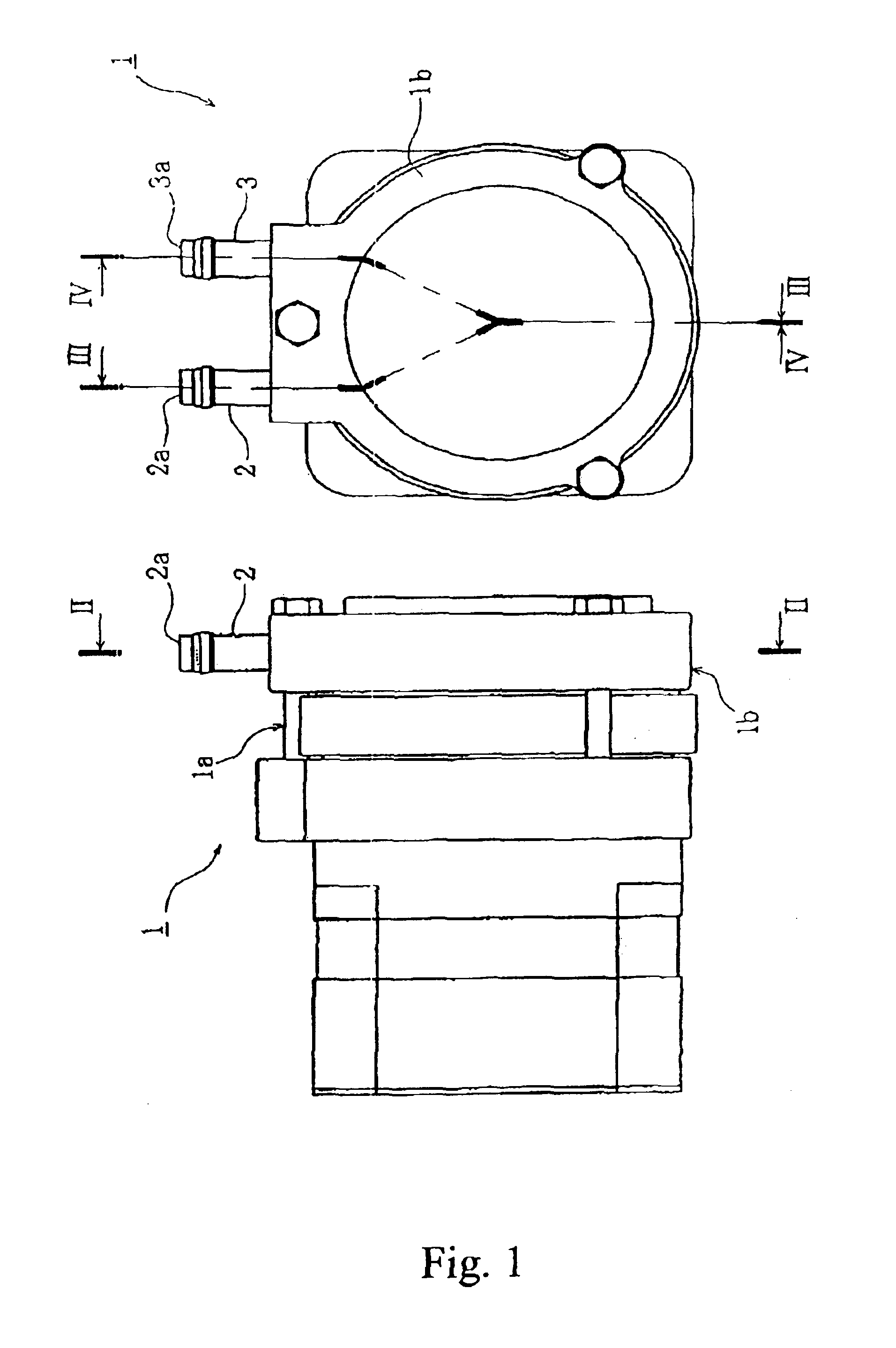
[0020]A preferred embodiment of the invention will be described below referring to the accompanying drawings. The self priming regenerative pump according to an embodiment of the invention is cable of relieving gasses mixed in the induced liquid without recourse to a gas-liquid separation tank of a specified capacity, and consists of a rear casing 1a and a front casing 1b as shown in FIG. 1 from the standpoint of its external appearance.

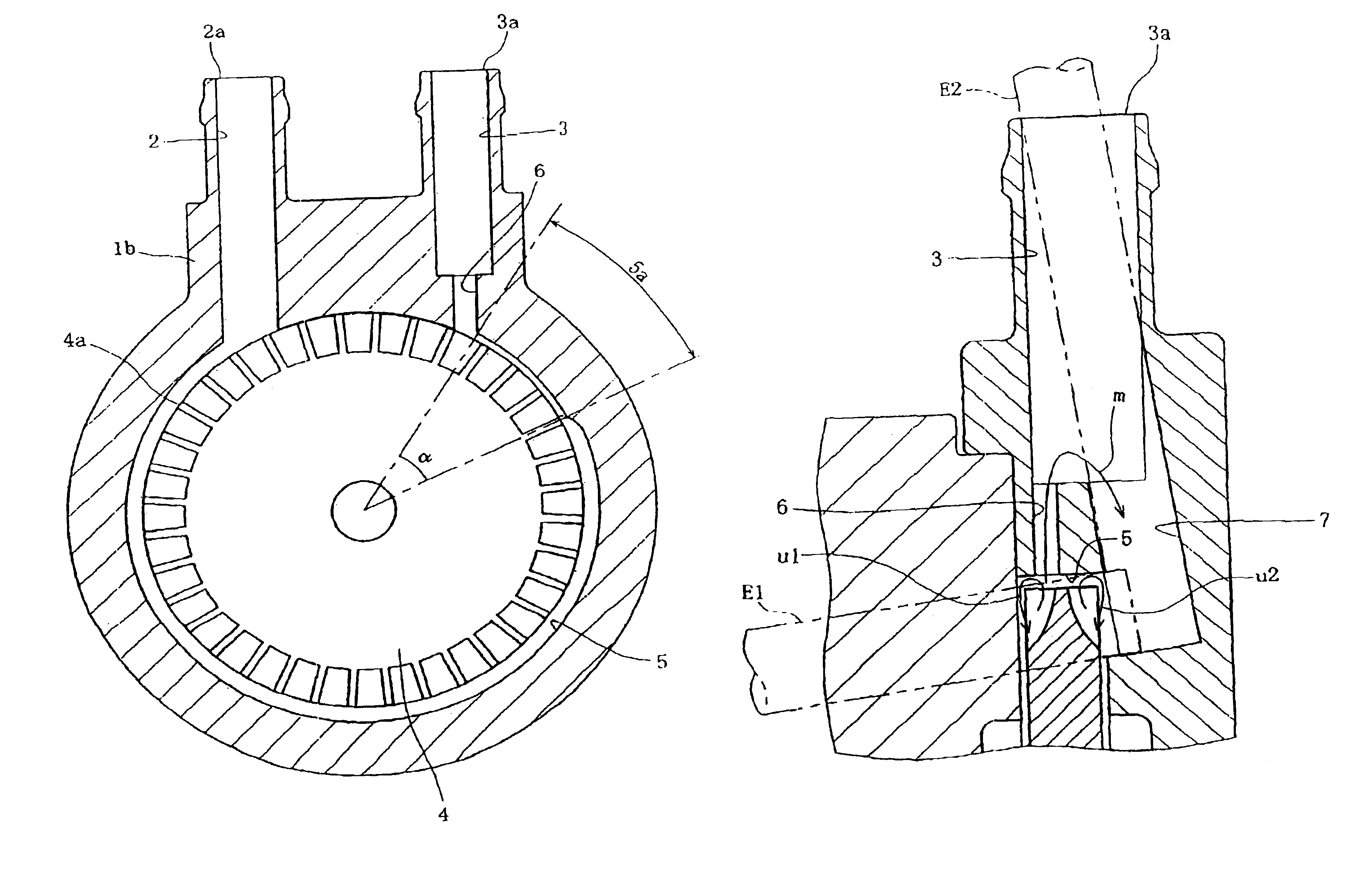
[0021]Rear casing 1 a houses a drive means such as an electric motor (not shown), and its output shaft 8 of the drive means sticks out and extends into front casing 1b as shown in FIG. 3. Said output shaft 8 is provided with a shaft seal 9 for preventing the liquid to leak outside, and its end extends into a cavity 1ba formed in front casing 1b.

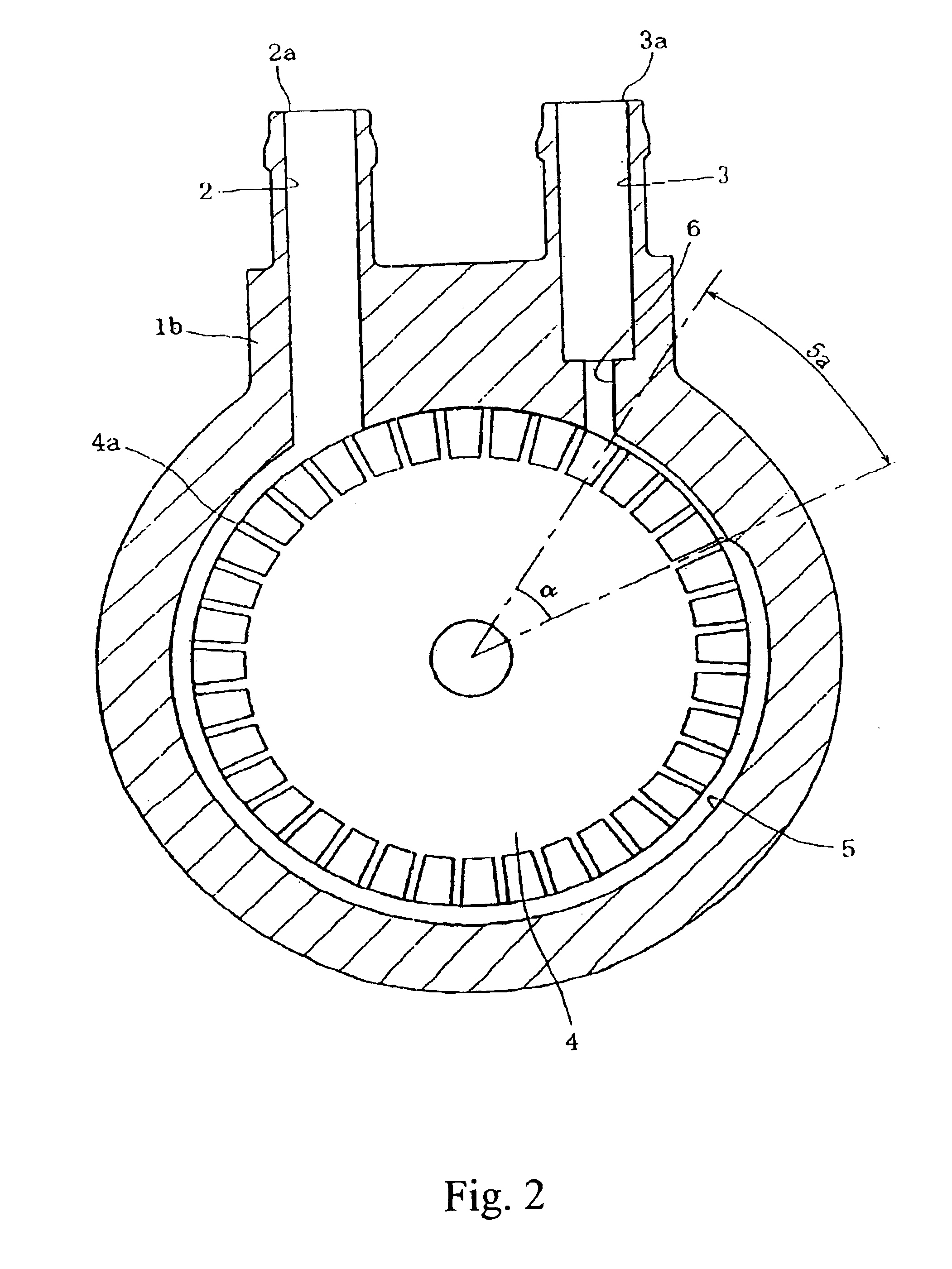
[0022]In the upper portion of front casing 1b has a suction flow passage 2 and a discharge flow passage 3 formed extending upward substantially in parallel with each other, and the openings of these suction f...


PUM


Abstract

A self priming regenerative pump comprising an impeller with a plurality of vanes formed on its periphery, casings 1a and 1b which house said impeller in a rotatable manner and a pressurizing passage consisting of a gap between said casing and the outer periphery of said impeller, further comprising: a small diameter part formed at a position communicating with pressurizing passage of a discharge flow passage, in particular, formed smaller than the diameter of a discharge port; and; a passage for communicating between discharge port side of smaller diameter part of discharge flow passage and pressurizing passage in order to allow the fluid in discharge flow passage to return to pressurizing passage, wherein said position communicating with pressurizing passage is outwardly offset from the center of the width of impeller.

Description

FIELD OF THE INVENTION[0001]The invention relates to a self priming regenerative pump which is capable of discharging gasses mixed in the induced fluid.DESCRIPTION OF THE RELATED ART[0002]A conventional self priming regenerative pump primarily consists of an impeller with a plurality of vanes formed on its periphery, a casing which houses said impeller in a rotatable manner and is equipped with a suction port for sucking a fluid and a discharge port for discharging the fluid formed thereon, and a pressurizing passage consisting of a gap between said casing and the outer periphery of said impeller. The pump sucks a fluid via the suction port, guides it through the pressurizing passage and discharges it via the discharge port by means of rotating the impeller while the casing is filled with the fluid.[0003]It is considered that fluid vortices develop between the vanes formed on the outer periphery of the impeller in such a self priming regenerative pump, thus causing a desirable disch...

Claims


Application Information

Patent Timeline
Patent Type & Authority Patents(United States)
IPC IPC(8): F04D9/02F04D5/00
CPCF04D5/002F04D5/007F05B2250/503
Inventor SUZUKI, HIROAKIUCHIUMI, ISAMU
Owner NIKKISO COMPANY
Why Eureka
Try Eureka