Package for electronic component, lid material for package lid, and production method for lid material

Inactive Publication Date: 2005-12-13
NEOMAX MATERIALS
View PDF15 Cites 16 Cited by
  • Summary
  • Abstract
  • Description
  • Claims
  • Application Information

AI Technical Summary

Benefits of technology

[0017]In accordance with the present invention, the lid has substantially the same construction as the lid material of the present invention described above. Therefore, the package obtained by fuse-bonding the lid to the case has a higher hermeticity, thereby extending the service life of the electroni

Problems solved by technology

Since the Ni layer of the lid is formed by the Ni plating, formation of pin holes in the Ni layer and contamination with an impurity such as an additive contained in a plating solution are inevitable.
The impurity present in the Ni layer reduces the ductilit

Method used


Image

  • Package for electronic component, lid material for package lid, and production method for lid material
  • Package for electronic component, lid material for package lid, and production method for lid material
  • Package for electronic component, lid material for package lid, and production method for lid material

Examples


example 1

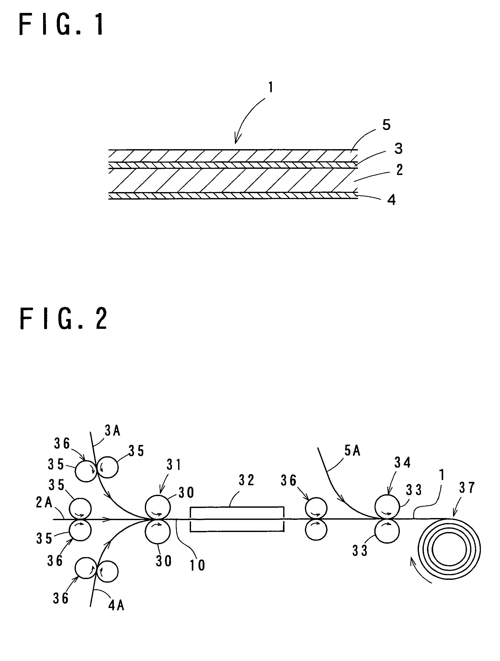
[0044]A 20-mm wide and 650-μm thick sheet of an Fe—Ni—Co alloy comprising 29 wt % Ni, 17 wt % Co and the balance Fe was prepared for use as a core sheet, and 20-mm wide and 40-μm thick pure Ni foils were prepared for use as Ni-based metal foils. The Ni-based metal foils 3A, 4A were superposed on opposite surfaces of the core sheet 2A, and the resulting stack was roll-pressed with a reduction ratio of 73% by the Ni-based metal foil press-bonding means 31 of the production apparatus shown in FIG. 2. Through this roll press operation, a laminate 10 of a 176-μm thick core layer and 11-μm thick Ni-based metal layers press-bonded onto the opposite surfaces of the core layer was obtained. A plurality of such laminates 10 were prepared in this manner, and diffusion-annealed under various annealing conditions in the annealing oven 32.

[0045]After the diffusion-annealing, the laminates 10 were subjected to a peel test for the Ni-based metal layers. In the peel test, a peel force per unit width...

example 2

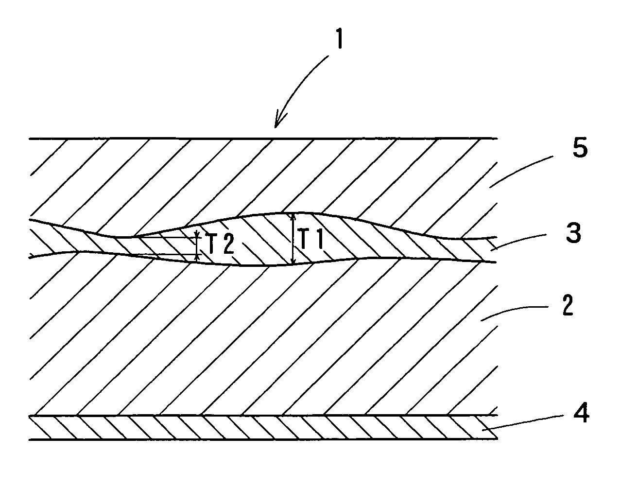
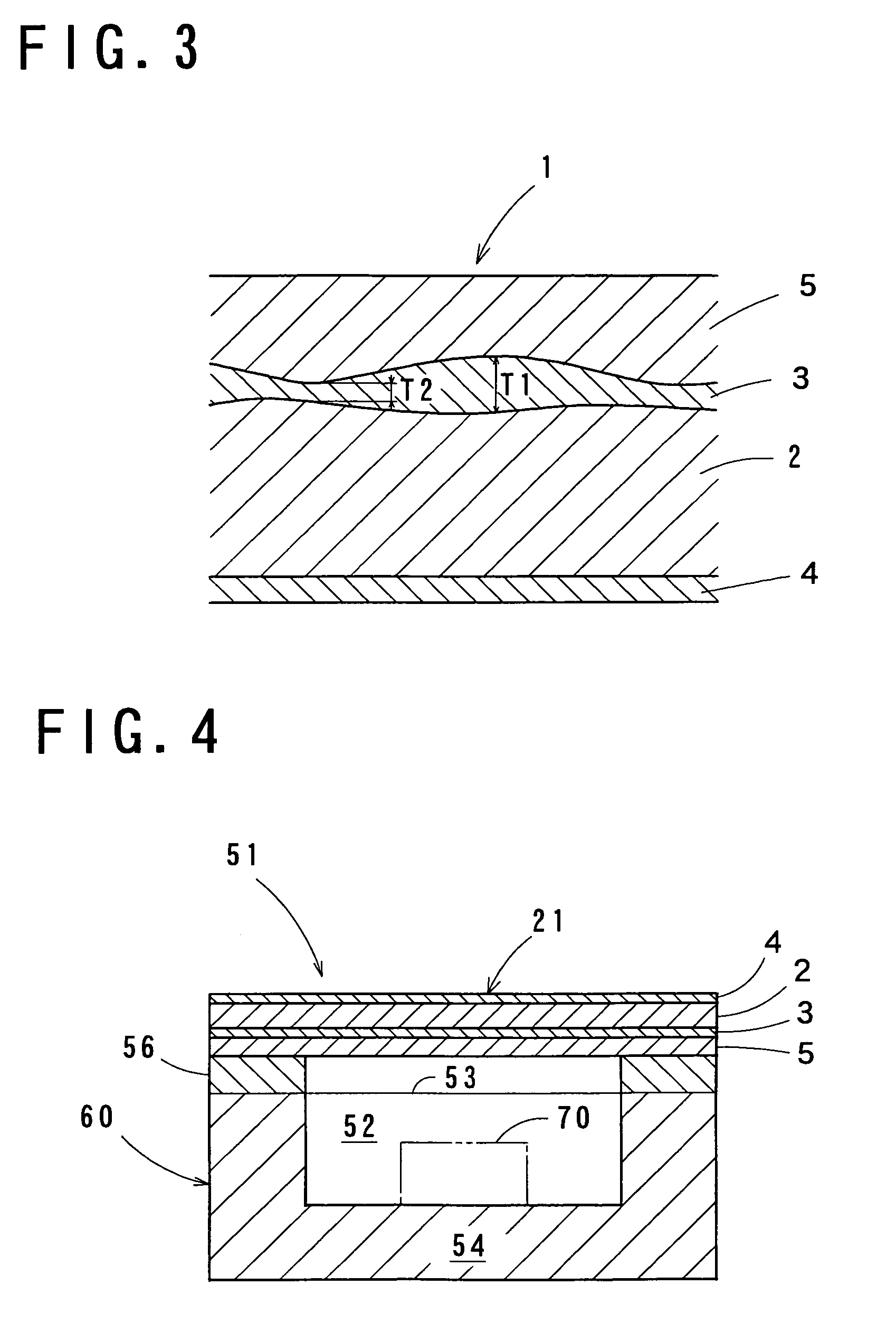
[0049]Lid materials 1 according to Example 2 had a basic construction as shown in FIG. 1. An Fe—Ni—Co alloy comprising 29 wt % Ni, 17 wt % Co and the balance Fe was used as the material for a core layer, a pure Ni was used as a Ni-based metal, and a Pb—Sn—Ag alloy comprising 62 wt % Sn, 2 wt % Ag and the balance Pb and an Sn—Ag alloy comprising 2 wt % Ag and the balance Sn were each used as a soft brazing material.

[0050]The lid materials 1 were each produced by the lid material production apparatus shown in FIG. 2. For the production of the lid material 1 by the production apparatus, a 20-mm wide and 1,300-μm thick core sheet 2A, 20-mm wide and 200-μm thick Ni-based metal foils 3A, 4A and a 20-mm wide and 100-μm thick brazing material foil 5A were used.

[0051]The Ni-based metal foils 3A, 4A were superposed on opposite surfaces of the core sheet 2A, and the resulting stack was roll-pressed with a reduction ratio of 65% by the Ni-based metal foil press-bonding means 31. Through this ro...


PUM

PropertyMeasurementUnit
Fractionaaaaaaaaaa
Fractionaaaaaaaaaa
Fractionaaaaaaaaaa

Abstract

A lid material is provided which comprises: a core layer composed of an Fe—Ni alloy or an Fe—Ni—Co alloy; a nickel-based (Ni-based) metal layer press- and diffusion-bonded onto the core layer and composed of a Ni-based metal, such as pure Ni, mainly comprising Ni; and a brazing material layer press-bonded onto the Ni-based metal layer. The Ni-based metal layer has a maximum-to-minimum thickness ratio T1/T2 of 1.4 to 15. The lid material is produced by press-bonding a Ni-based metal foil onto a core sheet for formation of the Ni-based metal layer on the core layer, then diffusion-annealing the Ni-based metal layer and the core layer, and press-bonding a brazing material foil onto the Ni-based metal layer with a reduction ratio of 30 to 65%.

Description

BACKGROUND OF THE INVENTION[0001]1. Field of the Invention[0002]The present invention relates to a package for housing an electronic component. The invention also relates to a lid material for a package lid and to a production method for the lid material.[0003]2. Description of Related Art[0004]Packages for housing various electronic components such as semiconductor devices (ICs) and piezoelectric vibrators generally comprise a case having an open top and a housing space for the electronic components, and a lid fuse-bonded to a peripheral upper surface of the case for hermetically sealing the housing space.[0005]The lid comprises a core plate such as formed of an iron-nickel (Fe—Ni) alloy, nickel (Ni) layers formed on opposite surfaces of the core plate, and a brazing material layer formed on one of the Ni layers by press-bonding a brazing material foil onto the Ni layer. The formation of the Ni layers is conventionally achieved by plating the core plate with Ni.[0006]The package is...

Claims


Application Information

Patent Timeline
IPC IPC(8): B23K20/00B32B15/01H01L21/48H01L23/06H01L23/02H05K10/00
CPCH01L21/4817H01L23/06H01L2924/01079Y10T428/12451Y10T428/12944Y10T428/12389Y10T428/12535H01L2924/16195H05K10/00
Inventor FUNAMOTO, KENICHINODA, HIDETOSHIISHIO, MASAAKI
Owner NEOMAX MATERIALS
Why Eureka
Try Eureka