Systems and methods of determining motion tool parameters in borehole logging

a technology of motion tool parameters and logging, which is applied in the field of borehole logging, can solve problems such as distortion, inaccurate measurement, and distortion of received signals, and achieve the effects of improving accuracy, improving accuracy, and improving accuracy

Inactive Publication Date: 2005-12-13
HALLIBURTON ENERGY SERVICES INC
View PDF77 Cites 30 Cited by
  • Summary
  • Abstract
  • Description
  • Claims
  • Application Information

AI Technical Summary

Benefits of technology

[0016]Accordingly, in one aspect, the invention is an apparatus for making borehole measurements using a logging tool, comprising: at least two accelerometers measuring motion parameters of the tool in a borehole, the motion parameters being measured in a tool reference frame; two or more magnetic induction senso

Problems solved by technology

Thus, for example, a shift in the sensitive volume of the logging tool caused by lateral motion of the tool relative to the borehole can distort the received signal and produce inaccurate measurements.
Such distortions can be especially problematic in logging-while-drilling (LWD) and measurement-while-drilling (MWD) environments, where the tool itself is subjected to severe vibration.
However, such placement is generally not possible in downhole tools because of design constraints, in particular owing to the need to have an open space within the center of the tool for a mud flow channel.
There are two main problems associated with this prior art approach.
Tool tilt away from vertical is sensed by the accelerometers

Method used


Image

  • Systems and methods of determining motion tool parameters in borehole logging
  • Systems and methods of determining motion tool parameters in borehole logging
  • Systems and methods of determining motion tool parameters in borehole logging

Examples


Embodiment Construction

[0041]The structure and function of the preferred embodiment can best be understood by reference to the attached drawings. Where the same reference numerals appear in multiple figures, the numerals refer to the same or corresponding structure in those figures.

A. The System of the Invention

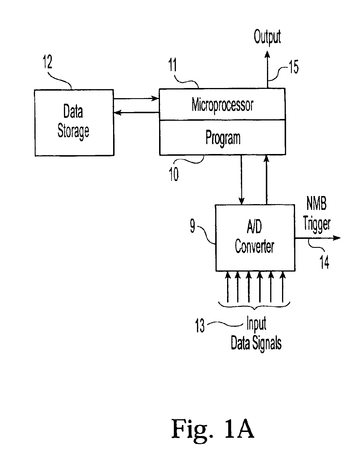
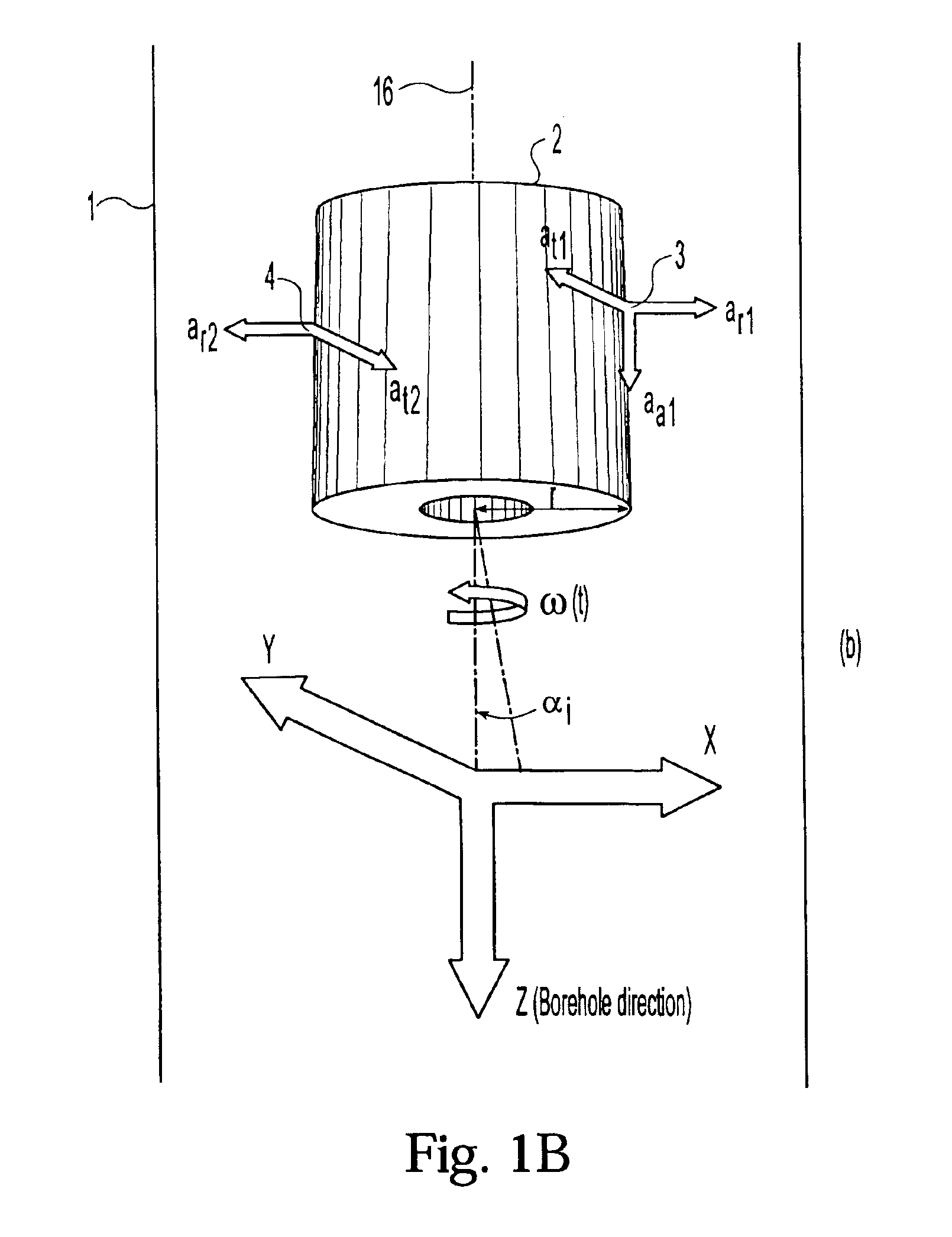
[0042]In a preferred embodiment, the system of the present invention for determining the lateral velocity of a drilling tool comprises at least two pairs of accelerometers placed opposite each other across the tool axis of rotation, a first and second magnetometer placed on the tool to provide detection of the tool's rotational magnetic phase relative to the earth's gravitational field, an interface for reading signals from the accelerometers and magnetometers, and a data processor for providing a corrected value of lateral tool velocity in the borehole frame of reference.

[0043]As shown in FIG. 1A, in a preferred embodiment of the system, the interface for reading data signals comprises electrical ...


PUM


Abstract

A system and method for calculating the lateral velocity of a rotating drilling tool within a borehole, the system comprising: a pair of accelerometers placed oppositely across the drilling tool axis of rotation and two magnetometers. The method comprises: reading tool radial acceleration signals ar1, ar2, and tangential acceleration signals, at1 and at3, obtained with a quadrature accelerometer detection system; reading Bx and By, the tool's magnetic phase data, from two orthogonally placed magnetometers; determining the rotational phase angle of the drilling tool relative to the earth's gravity field by first determining the tool's magnetic phase, and the phase shift between the tool's magnetic phase and gravity phase; and processing the foregoing data to yield a lateral tool velocity which optionally compensates for the effect of gravity on the accelerometers, or converts the lateral tool velocity from the tool reference frame to the borehole reference frame, or does both.

Description

CROSS-REFERENCE TO RELATED APPLICATIONS[0001]The present application is a continuation of U.S. application Ser. No. 09 / 882,228, which was filed on Jun. 14, 2001 and issued as U.S. Pat. No. 6,518,756 on Feb. 11, 2003.FIELD OF THE INVENTION[0002]The present invention generally relates to borehole logging and more particularly, to systems and methods for determining parameters of the motion of a logging tool in a borehole and compensating for this motion in the logging data.BACKGROUND OF THE INVENTION[0003]Knowledge of the motion parameters of a logging tool relative to a borehole is important for obtaining accurate downhole measurement signals. Thus, for example, a shift in the sensitive volume of the logging tool caused by lateral motion of the tool relative to the borehole can distort the received signal and produce inaccurate measurements. Such distortions can be especially problematic in logging-while-drilling (LWD) and measurement-while-drilling (MWD) environments, where the tool...

Claims


Application Information

Patent Timeline
IPC IPC(8): E21B47/00
CPCE21B47/00G01V3/32G01V11/005
Inventor MORYS, MARIANGOODMAN, GEORGE D.PRAMMER, MANFRED G.
Owner HALLIBURTON ENERGY SERVICES INC
Why Eureka
Try Eureka