Microelectromechanical isolating circuit

a micro-electromechanical and isolating circuit technology, applied in the direction of electrostrictive/piezoelectric relays, electrostatic generators/motors, electrical apparatus, etc., can solve the problems of increasing the cost of additional circuitry, limiting the power, and conventional techniques

Inactive Publication Date: 2005-12-13
ROCKWELL AUTOMATION TECH
View PDF79 Cites 50 Cited by
  • Summary
  • Abstract
  • Description
  • Claims
  • Application Information

AI Technical Summary

Benefits of technology

[0018]Thus, it is another object of the invention to provide an isolator that may control the effective input impedance at the input terminals while preserving isolation between input and output terminals. Such an isolator may be useful for input circuits that must present a certain load, for example, those used in a programmable logic controller.

Problems solved by technology

Isolation may also imply a degree of power limiting that prevents faults on one side of the isolation from affecting circuitry on the other side of the isolation.
There are drawbacks to these conventional techniques.
This additional circuitry adds considerable expense.
Second, the volume occupied by the capacitor or transformer may preclude its use in certain applications where many independently isolated circuits must be placed in close proximity or isolation is required-on a very small mechanical scale, for example, on an integrated circuit.

Method used


Image

  • Microelectromechanical isolating circuit
  • Microelectromechanical isolating circuit
  • Microelectromechanical isolating circuit

Examples


Embodiment Construction

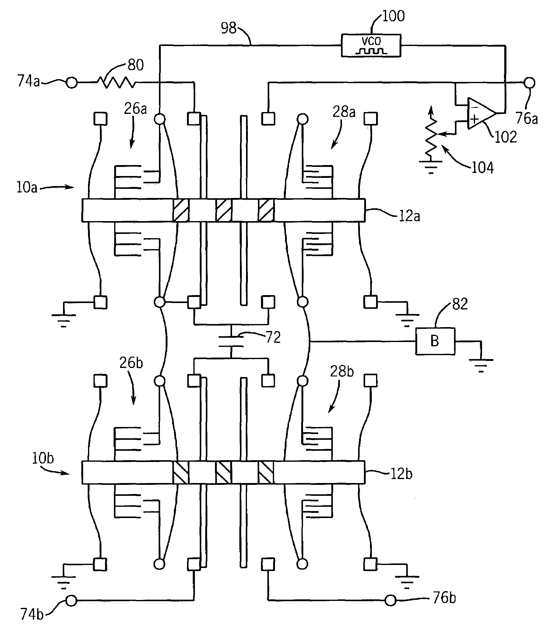
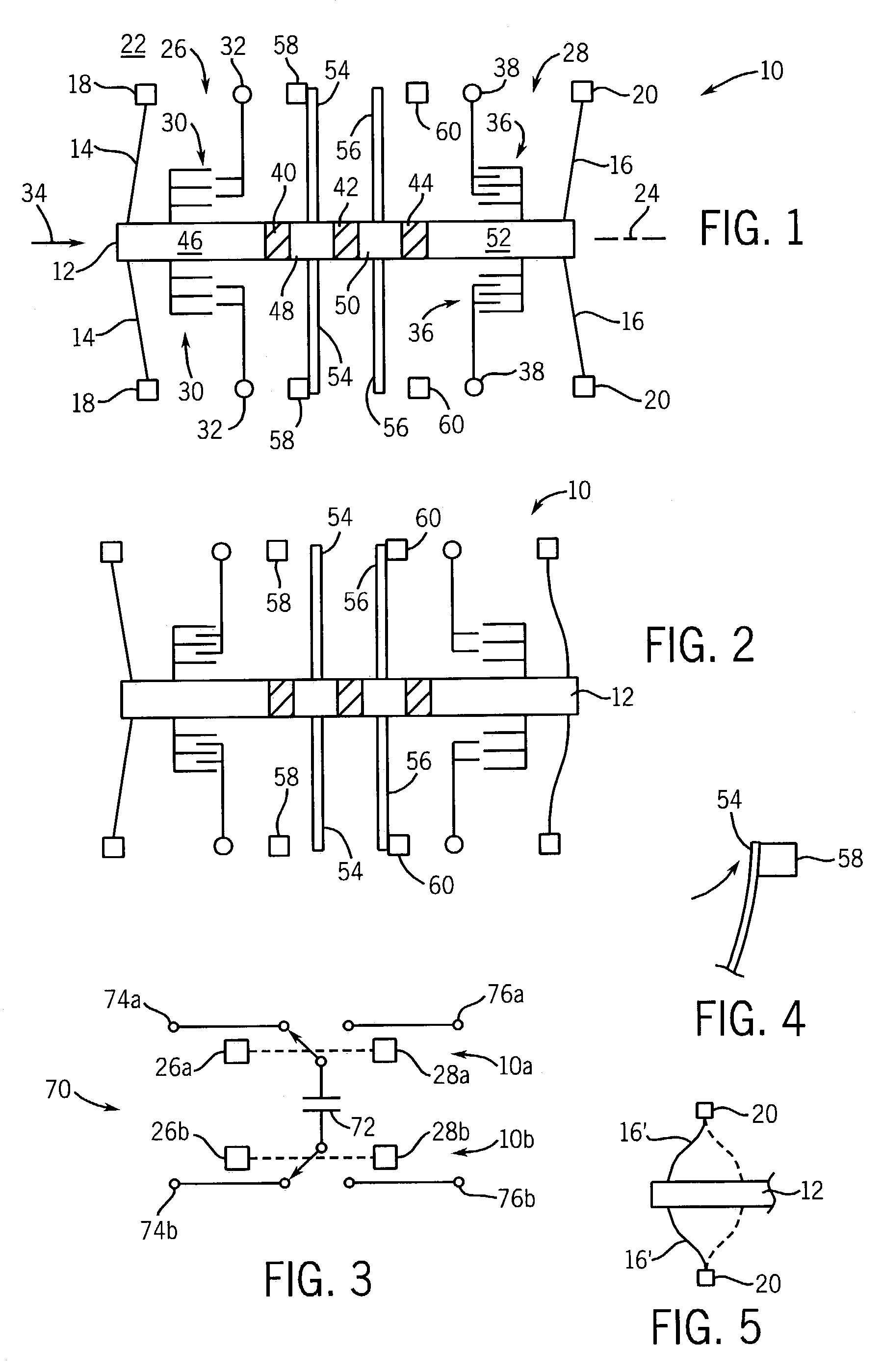
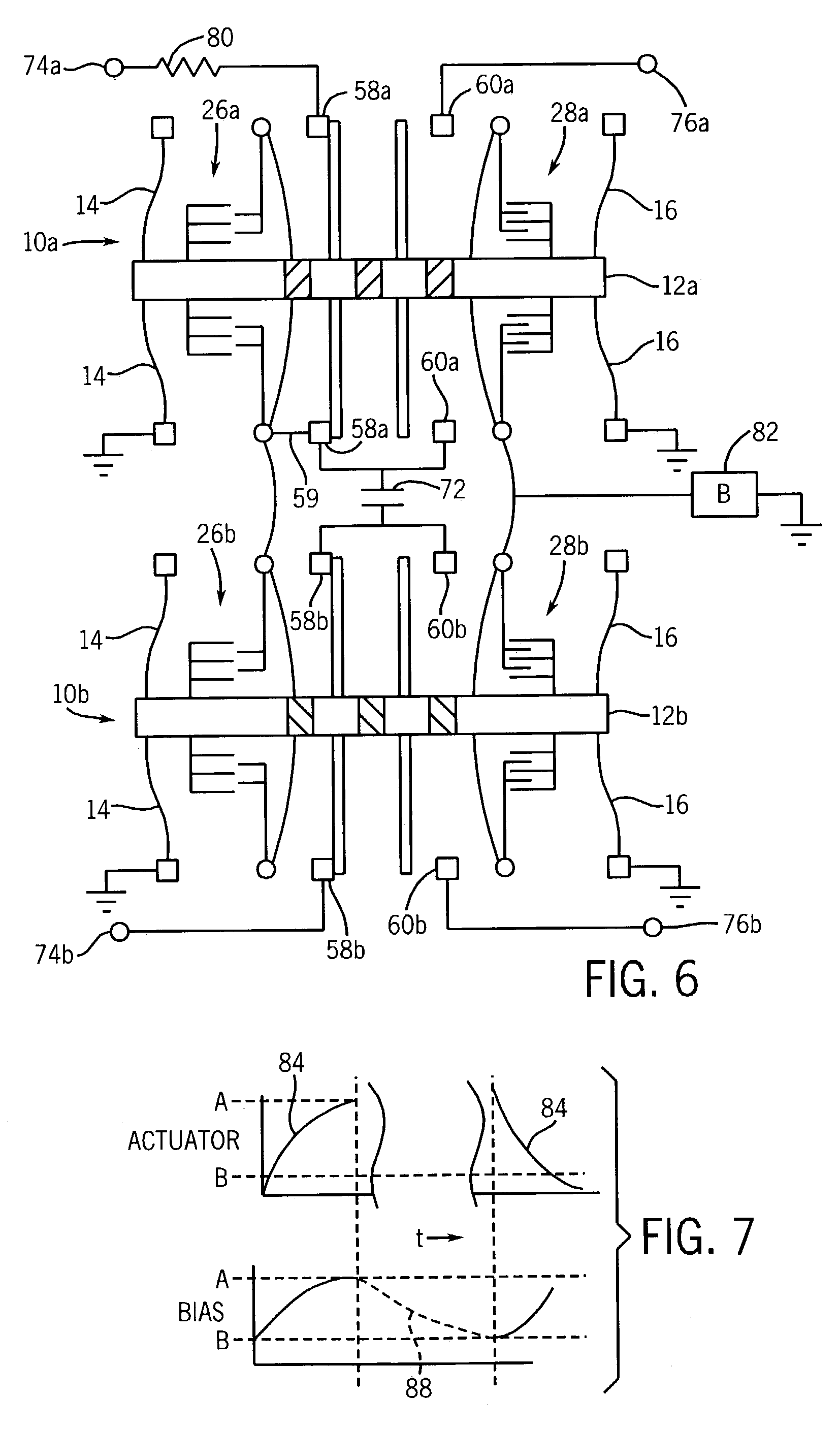
[0037]Referring now to FIG. 1, a MEMS double pole, double throw switch 10 may include a longitudinal beam 12 supported on two pairs of transverse arms 14 and 16 extending from opposite sides of opposite ends of the longitudinal beam 12. The transverse arms 14 and 16 are also attached to stationary pylons 18 and 20 that are fixed with respect to an underlying substrate 22. As supported by flexing of the transverse arms 14 and 16, the longitudinal beam 12 is free to move along a longitudinal axis 24.

[0038]The longitudinal beam 12 may support an input actuator 26 and a bias actuator 28. As shown, the input actuator 26 is positioned at the end of the longitudinal beam 12 near transverse arms 14 and consists of two pairs of interdigitated capacitor plates 30. One half of each pair of interdigitated capacitor plates 30 are supported by the longitudinal beam 12 extending in opposite directions from the longitudinal beam 12. The remaining half of each pair of interdigitated capacitor plates...


PUM


Abstract

Microelectromechanical (MEMS) switches are used to implement a flying capacitor circuit transferring of electrical power while preserving electrical isolation for size critical applications where transformers or coupling capacitors would not be practical. In one embodiment, the invention may be used to provide input circuits that present a programmable input impedance. The circuit may be modified to provide for power regulation.

Description

CROSS-REFERENCE TO RELATED APPLICATIONSSTATEMENT REGARDING FEDERALLY SPONSORED RESEARCH OR DEVELOPMENTBACKGROUND OF THE INVENTION[0001]The present invention relates to microelectromechanical systems (MEMS) and in particular to MEMS for transferring electrical power while maintaining electrical isolation between the points of transfer.[0002]MEMS are extremely small machines fabricated using integrated circuit techniques or the like. The small size of MEMS makes possible the mass production of high speed, low power, and high reliability mechanisms that could not be realized on a larger scale.[0003]Often in electrical circuits, it is desired to transfer power between two points while maintaining electrical isolation between those points. Isolation, in this context, means that there is no direct current (DC) path between the points of transfer. Isolation may also imply a degree of power limiting that prevents faults on one side of the isolation from affecting circuitry on the other side...

Claims


Application Information

Patent Timeline
Patent Type & Authority Patents(United States)
IPC IPC(8): H01H59/00
CPCH01H59/0009
Inventor KNIESER, MICHAEL J.HARRIS, RICHARD D.POND, ROBERT J.SZABO, LOUIS F.DISCENZO, FREDERICK M.HERBERT, PATRICK C.KRETSCHMANN, ROBERT J.LUCAK, MARK A.
Owner ROCKWELL AUTOMATION TECH
Why Eureka
Try Eureka