Projection lens apparatus and projection type image display apparatus

a projection lens and projection lens technology, applied in the field of projection lens apparatus and projection type image display apparatus, can solve the problem of drawing a short back focus of about 20 mm, and achieve the effect of more versatility of possible compensation, effectively compensating off-axis ray aberration, and effectively compensating on-axis ray aberration

Inactive Publication Date: 2005-12-13
HITACHI LTD
View PDF22 Cites 12 Cited by
  • Summary
  • Abstract
  • Description
  • Claims
  • Application Information

AI Technical Summary

Benefits of technology

[0010]Power distribution of the first to third lens groups as defined above allows the projection lens apparatus to compensate satisfactorily various kinds of aberration, while the compactness and the wide-angle of the apparatus are achieved.
[0014]The projection lens apparatus according to the present invention also may allow the first, second and third lens groups to have a spherical surfaces. If every lens group has an aspherical surface thereat, the first and third lens groups compensate aberration such as distortion aberration and chromatic aberration of magnification on the aspherical surfaces thereof, and the second lens group compensates aberration of an on-axis ray on its aspherical surface. This configuration permits the lens apparatus to have more versatility of possible compensation of aberration, accordingly to perform further compensation of aberration.
[0015]In particular, using an aspherical surface as an emission surface of a third lens of the third lens group, having a large off-axis ray height, serves to effectively compensate aberration of an off-axis ray. Using an aspherical surface also as an incidence surface of a second lens of the second lens group serves to most effectively compensate aberration of an on-axis ray.
[0016]Using a plastic lens as a first lens of the first lens group, having a largest diameter among lenses of the projection lens apparatus according to the present invention, allows the apparatus according to the present invention to reduce its weight. However, since the plastic lens changes in shape according to changes in temperature and humidity, the lens characteristics thereof such as lens focus and MTF deteriorates, when the plastic lens has a large power. The condition below is intended to control the power of the plastic lens so that the lens characteristics do not deteriorate even when the plastic lens changes in shape according to changes in temperature and humidity.7<|fL1 / f|  (5)
[0017]A typical plastic lens has poor accuracy in shape and large deviations in shape accuracy compared to a glass lens. To suppress the deterioration of the plastic lens having deviations in shape accuracy, a ray is made incident on the plastic lens, in a direction substantially perpendicular to the plastic lens, serving as the first lens of the first lens group in the projection lens apparatus according to the present invention. This configuration allows the plastic lens to have a larger tolerance in shape and enhance its manufacturability.

Problems solved by technology

Although the image display apparatus equipped with a CRT is capable of electrically compensating distortion aberration of a projection image, the image display apparatus equipped with a liquid crystal display element or a DMD element is not.
A projection type lens apparatus using liquid display elements also has been developed as set forth, e.g., in JP-A-11-149041 specification, however, it has a drawback of a short back focus of about 20 mm.

Method used


Image

  • Projection lens apparatus and projection type image display apparatus
  • Projection lens apparatus and projection type image display apparatus
  • Projection lens apparatus and projection type image display apparatus

Examples


Embodiment Construction

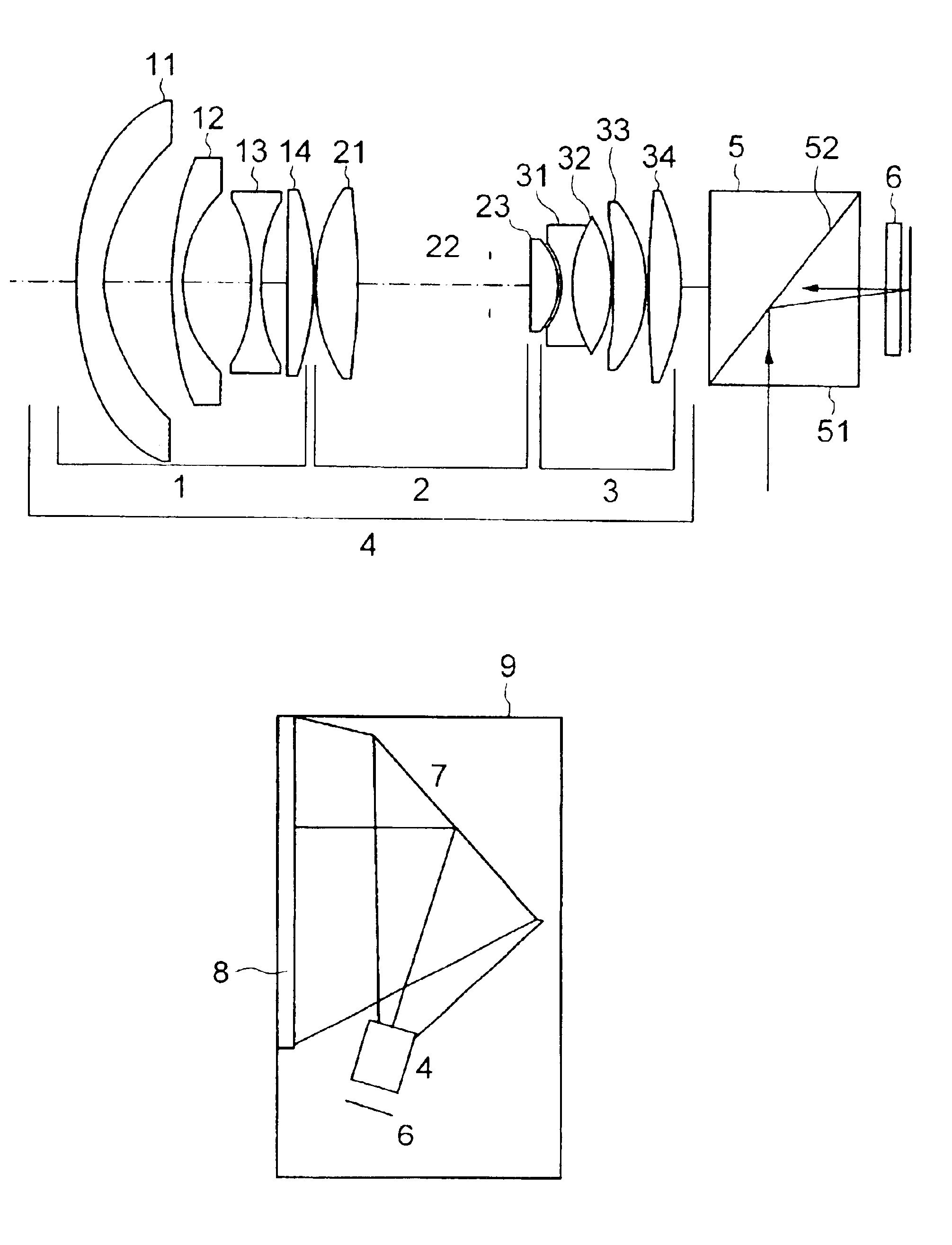
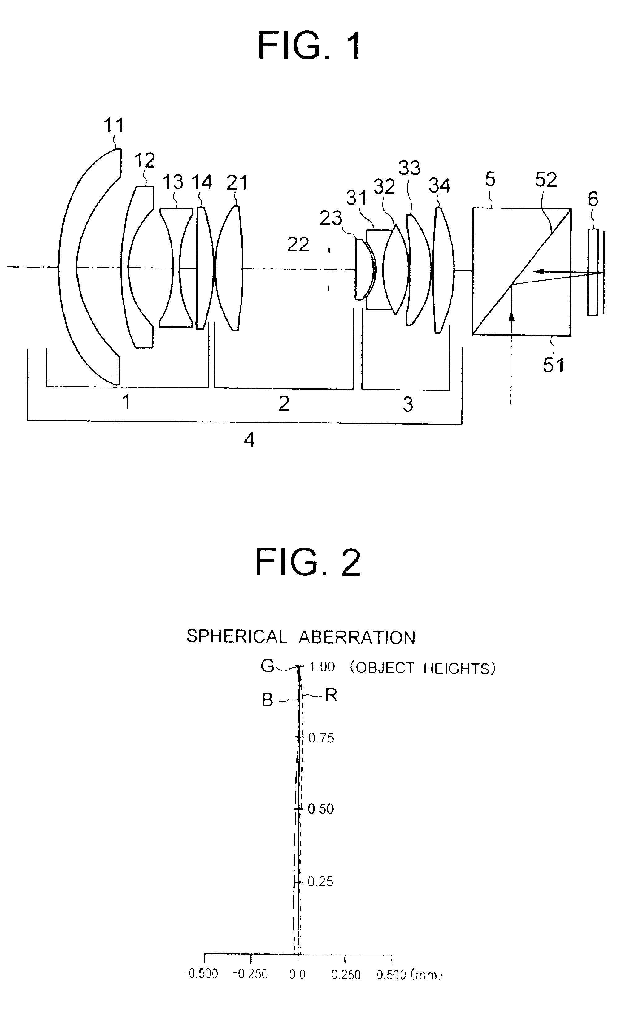
[0042]Referring now to the attached drawings, preferred embodiments of the present invention will be described. FIGS. 1, 5, 9, 13, and 17 are illustrations of projection lens apparatuses according to the embodiments of the present invention. The following description will be focused mainly on FIG. 1, and descriptions on FIGS. 5, 9, 13, and 17 will be omitted since these figures are considered to be understood from data in Tables 2 to 5 and on the analogy of the description on FIG. 1.

[0043]FIG. 1 is a schematic view of a first embodiment of the projection lens apparatus and its associated optical components showing, from a projection screen (not shown) or the left side of the plane of the figure, a first lens group 1, a second lens group 2, a third lens group 3, a total reflection prism (hereinafter, referred to as a TIR prism) 5, and a DMD element 6 in this order. The above three lens groups 1 to 3 constitute a projection lens apparatus 4. A ray emitted from a light source is made i...


PUM

PropertyMeasurementUnit
wavelengthsaaaaaaaaaa

Abstract

A projection type image display apparatus having an image display element outputting an image ray, a projection lens apparatus for performing overhead projection of the image ray from the image display element, the projection lens apparatus having a plurality of lens elements, a reflection mirror reflecting the image ray from the projection lens apparatus, and a screen on which the image ray reflected by the reflection mirror is projected. An optical axis of the projection lens apparatus is decentered from a center of the screen.

Description

CROSS REFERENCE TO RELATED APPLICATION[0001]This is a continuation of U.S. application Ser. No. 09 / 903,510, filed Jul. 13, 2001, now U.S. Pat. No. 6,560,041 the subject matter of which is incorporated by reference herein.BACKGROUND OF THE INVENTION[0002]1. Field of the Invention[0003]The present invention relates to a projection lens apparatus for allowing a source light to be made incident in an image display apparatus so that an overhead projection of the reflected light or the transmitted light is performed on a projection screen, and also relates to a projection type image display apparatus equipped with the projection lens apparatus.[0004]2. Description of the Prior Art[0005]The main stream of a projection type image display apparatus has been a type that performs an overhead projection of an image formed in a CRT. In order to improve the efficiency of light usage, and reduce the size and the weight of the apparatus, a projection type image display equipped with a liquid crysta...

Claims


Application Information

Patent Timeline
Patent Type & Authority Patents(United States)
IPC IPC(8): G02B13/24G02B13/02G02B13/18G02F1/13G02F1/1335G03B21/00G03B21/10
CPCG02B13/02G03B21/26
Inventor IKEDA, HIDEHIROYATSU, MASAHIKOHIRATA, KOJIIKOMA, JUNICHI
Owner HITACHI LTD
Why Eureka
Try Eureka