Method and apparatus for DC offset removal in a radio frequency communication channel

a radio frequency communication channel and offset removal technology, applied in the field of electromagnetic (em) signal frequency conversion, can solve the problems of limited operation speed of conventional signal processing technology, inability to easily demodulate a baseband signal from a higher frequency modulated carrier signal directly, and inability to work well outside the frequency range of conventional down converters designed around specific frequencies or frequency ranges. to achieve the effect of reducing and/or eliminating dc offset voltages

Inactive Publication Date: 2005-12-13
PARKER VISION INC
View PDF688 Cites 84 Cited by
  • Summary
  • Abstract
  • Description
  • Claims
  • Application Information

AI Technical Summary

Problems solved by technology

However, because conventional signal processing technology is limited in operational speed, conventional signal processing technology cannot easily demodulate a baseband signal from higher frequency modulated carrier signal directly.
As a result, conventional down-converters are designed around specific frequencies or frequency ranges and do not work well outside their designed frequency range.
These amplifiers, down-converters, and other components in a receiver channel create unwanted DC offset voltages.
Any DC offset in the receiver channel has the effect of competing with the signal of interest, producing a statistical bias much like an interference.
Furthermore, the DC offset may cause the receiver channel to become saturated, such that a voltage rail is reached or exceeded.
In such situations, the information signal may not be recoverable at all.

Method used


Image

  • Method and apparatus for DC offset removal in a radio frequency communication channel
  • Method and apparatus for DC offset removal in a radio frequency communication channel
  • Method and apparatus for DC offset removal in a radio frequency communication channel

Examples


Embodiment Construction

Table of Contents

1. Introduction

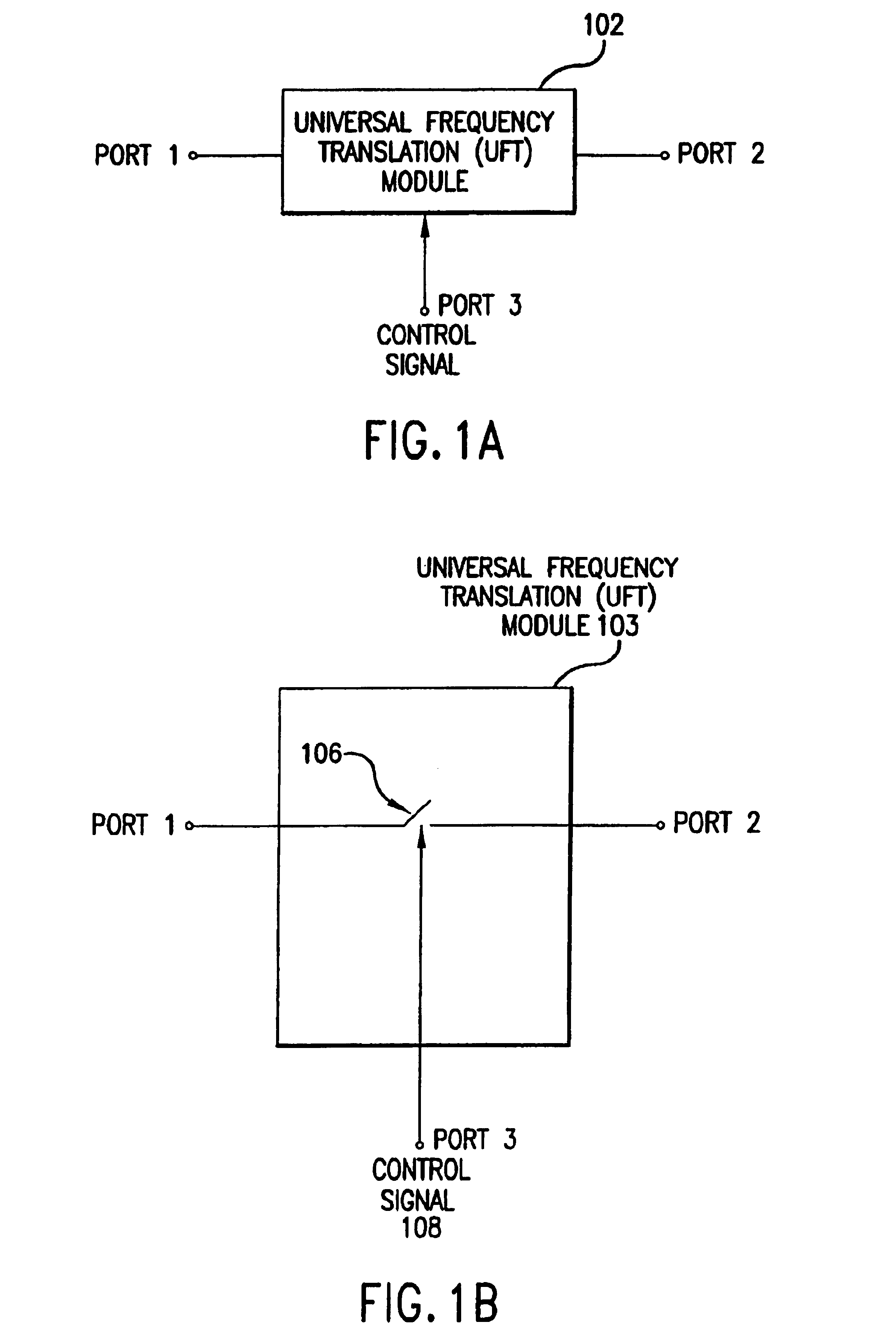
2. Universal Frequency Translation

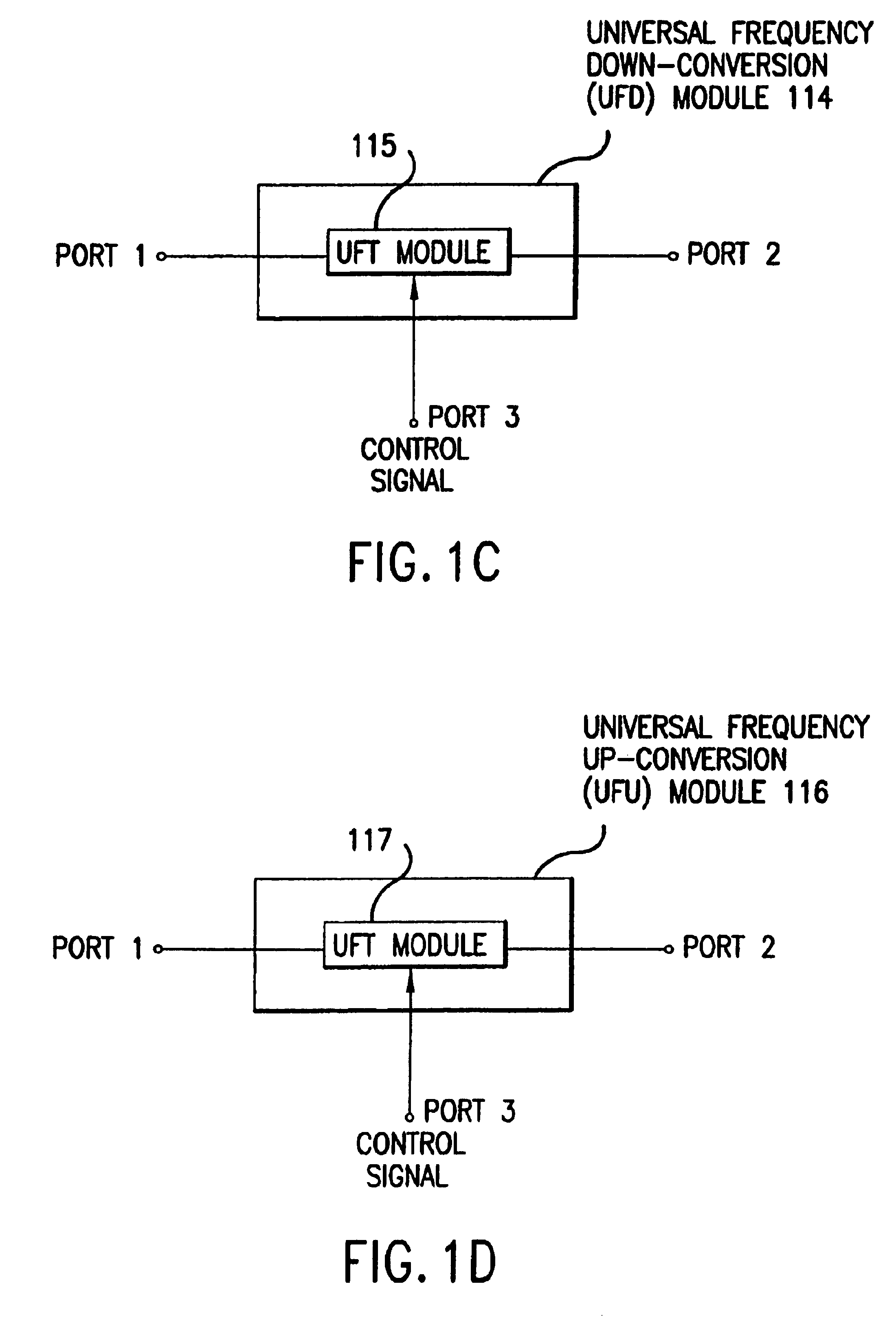
[0085]2.1 Frequency Down-Conversion

[0086]2.2 Optional Energy Transfer Signal Module

[0087]2.3 Impedance Matching

[0088]2.4 Frequency Up-Conversion

[0089]2.5 Enhanced Signal Reception

[0090]2.6 Unified Down-Conversion and Filtering

3. Example Down-Converter Embodiments of the Invention

[0091]3.1 Receiver Embodiments[0092]3.1.1 In-Phase / Quadrature-Phase (I / Q) Modulation Mode Receiver Embodiments

4. DC Offset and Circuit Gain Considerations and Corrections

[0093]4.1 Overview of DC Offset

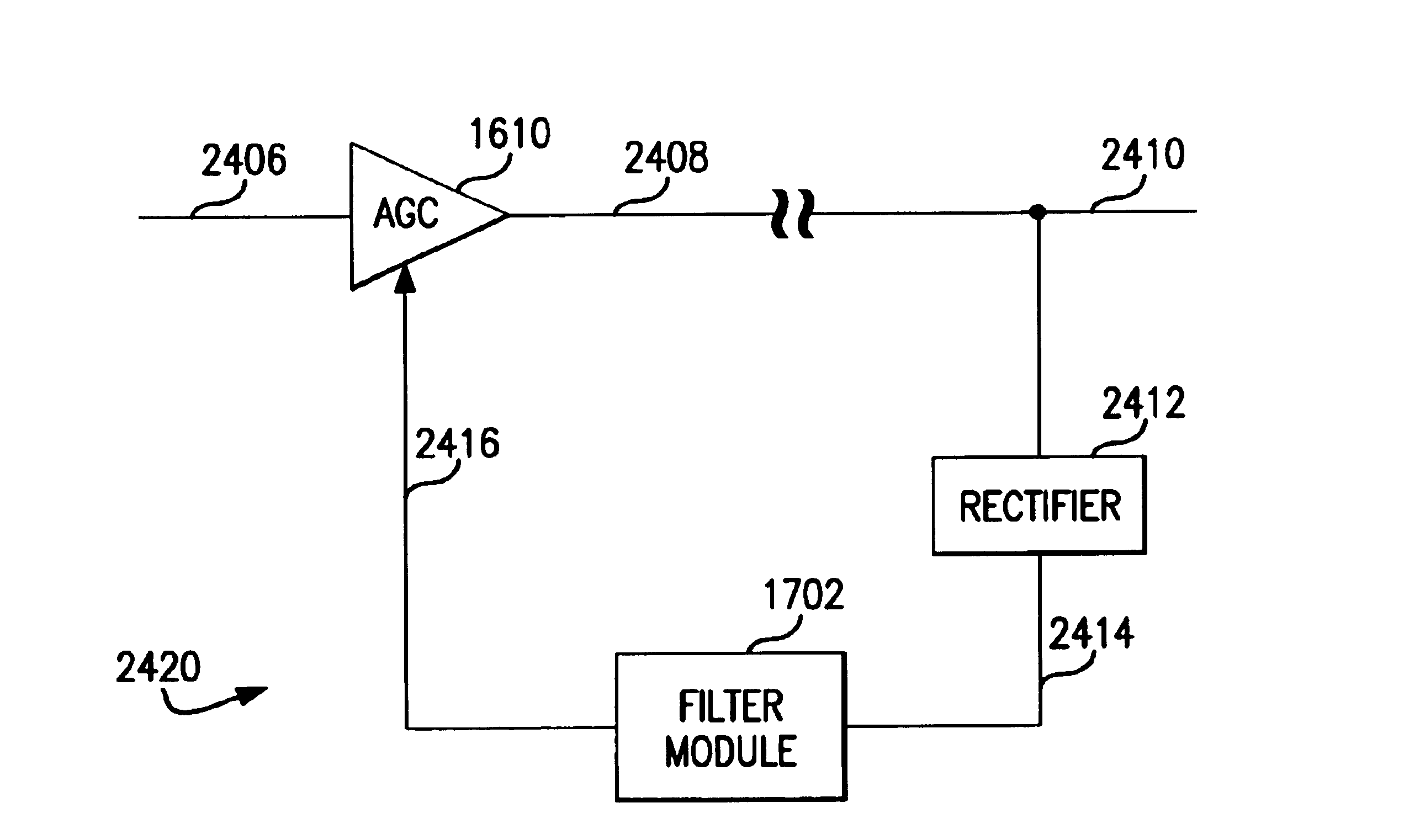
[0094]4.2 Exemplary Communications System Receiver Channel

[0095]4.3 Filter Module Embodiments of the Present Invention[0096]4.3.1 Active Variable Resistor of the Present Invention[0097]4.3.2 Control Signal Embodiments[0098]4.3.3 Operational Embodiments of the Present Invention[0099]4.3.4 Example Filter Module Applications[0100]4.3.4.1 Example Receiver Channel Application[0101]4.3.4.2 Example AGC Feedback Path Applications

5. Conclusion

1. Introduct...


PUM


Abstract

A filter module for reducing a DC offset voltage in a radio frequency communication channel is described. A first capacitor is coupled between a first differential input node and a first differential output node. A second capacitor is coupled between a second differential input node and a second differential output node. An active variable resistor is coupled between the first differential output node and the second differential output node. The active variable resistor receives a control signal. The control signal adjusts the value of the active variable resistor, which adjusts the frequency response of the filter module. The rate at which the filter module reduces DC offset voltages is thereby adjusted. The filter module is also adaptable to single-ended applications.

Description

CROSS-REFERENCE TO RELATED APPLICATIONS[0001]This application claims the benefit of U.S. Provisional Application No. 60 / 384,834, filed Jun. 4, 2002, which is herein incorporated by reference in its entirety.[0002]The following applications of common assignee are related to the present application, and are herein incorporated by reference in their entireties:[0003]“Method and System for Down-Converting Electromagnetic Signals,” Ser. No. 09 / 176,022, filed Oct. 21, 1998.[0004]“Method and System for Frequency Up-Conversion,” Ser. No. 09 / 176,154, filed Oct. 21, 1998.[0005]“Integrated Frequency Translation And Selectivity,” Ser. No. 09 / 175,966, filed Oct. 21, 1998.[0006]“Method and System for Down-converting an Electromagnetic Signal, and Transforms for Same, and Aperture Relationships,” Ser. No. 09 / 550,644, filed Apr. 14, 2000.[0007]“Method, System, and Apparatus for Balanced Frequency Up-conversion of a Baseband Signal,” Ser. No. 09 / 525,615, filed Mar. 14, 2000.[0008]“DC Offset, Re-radi...

Claims


Application Information

Patent Timeline
Patent Type & Authority Patents(United States)
IPC IPC(8): H04B1/30
CPCH04B1/30
Inventor RAWLINS, GREGORY S.BROWN, KEVINRAWLINS, MICHAEL W.SORRELLS, DAVID F.
Owner PARKER VISION INC
Why Eureka
Try Eureka