
Battery-powered carving knife having a rechargeable battery pack

a battery pack and battery-powered technology, applied in the field of battery-powered knives, can solve the problems of heavy mechanism, unergonomically pleasing device, bulky handgrip,

Inactive Publication Date: 2005-12-20
KDW COMPANY
View PDF33 Cites 20 Cited by
  • Summary
  • Abstract
  • Description
  • Claims
  • Application Information

AI Technical Summary

Benefits of technology

[0026]FIG. 19 is a perspective view of the rechargeable battery pack depicted in FI

Problems solved by technology

One of the drawbacks to existing products, whether electrically driven or battery-powered, is that the motor is located in the housing in a position such that the motor and / or the battery forms a counterweight to the knife blades, such that the weight must be counteracted by the user by a further carving force to enable the meat to be cut.
This provides for a device which is not very ergonomically pleasing to the user and feels very awkward during such use.
All of these mechanisms show a very heavy weight in the area where the casing would be gripped by the user as well as provide a very bulky handgrip for such use.
Yet further the device is not very compact as the motor includes the gear drive facing forward which causes a serial arrangement of the components, that is, the batteries-motor-gear drive-knife, causing a stack up of dimensions resulting in an elongate and bulky end product.
One design, shown in U.S. Pat. No. 5,230,155 shows a motor having the drive shaft facing rearward, but once again the weight distribution is not optimum, as the motor is placed midway within the housing as an extendable and retractable knife assembly is positioned at the front part of the housing.
This not only causes a weight distribution issue, but also provides a very bulky handgrip section making the design difficult for the user.

Method used


Image

  • Battery-powered carving knife having a rechargeable battery pack
  • Battery-powered carving knife having a rechargeable battery pack
  • Battery-powered carving knife having a rechargeable battery pack

Examples


Embodiment Construction

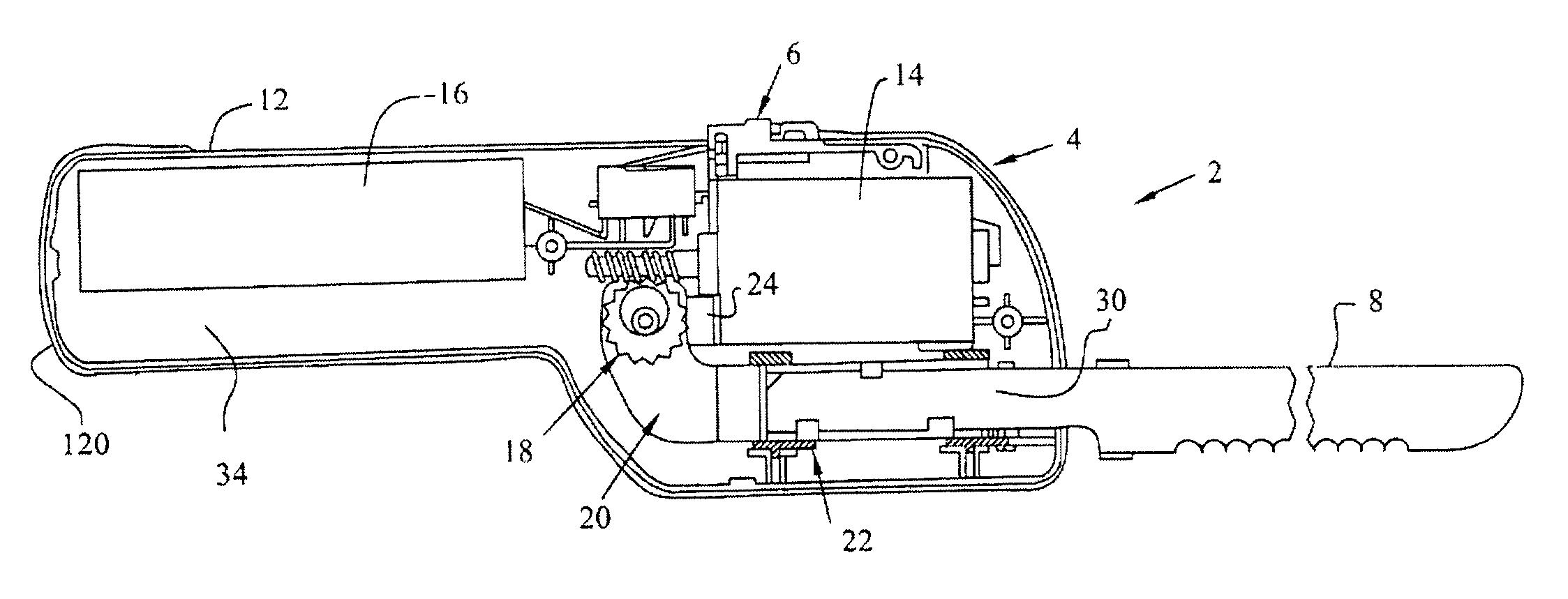
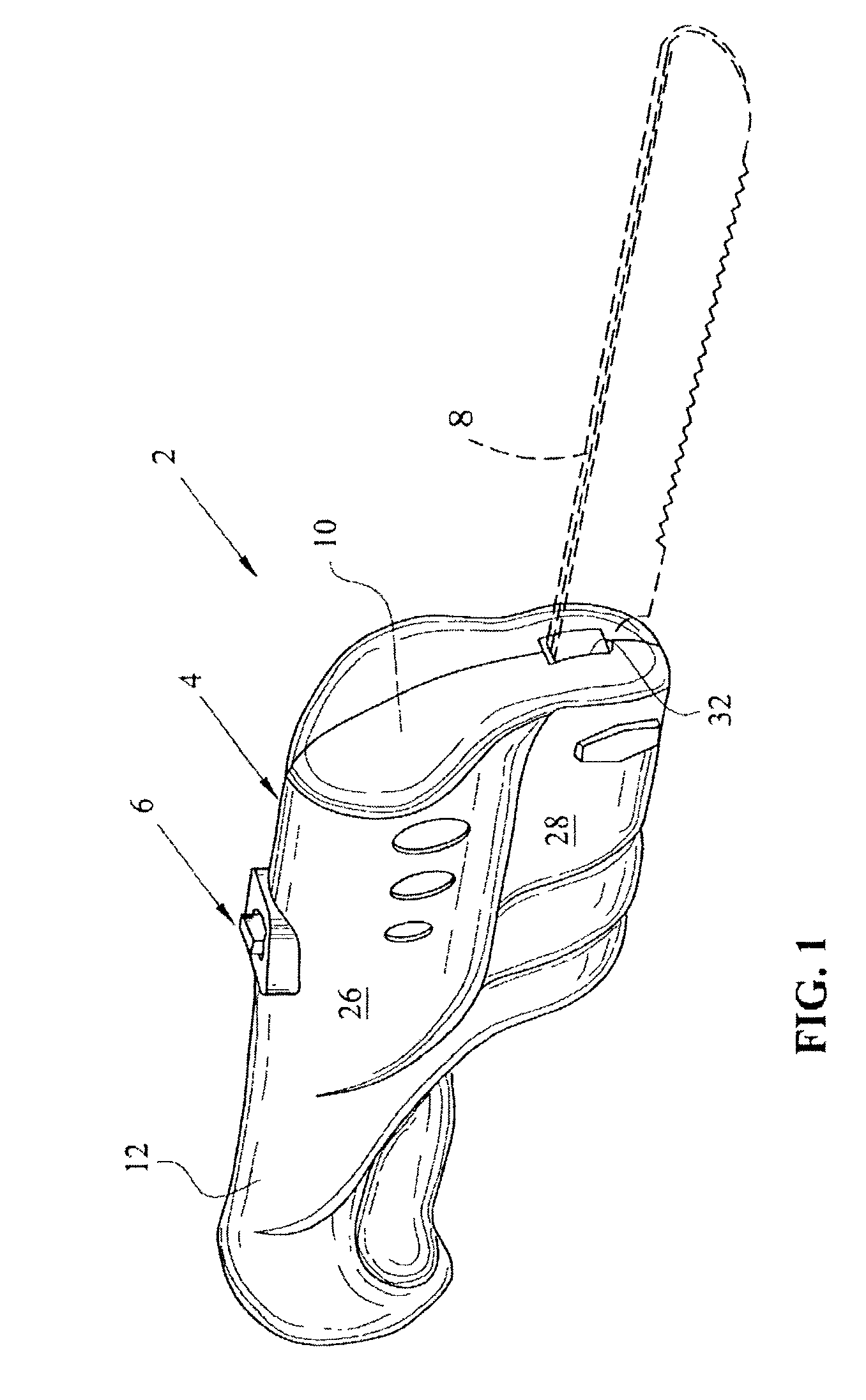
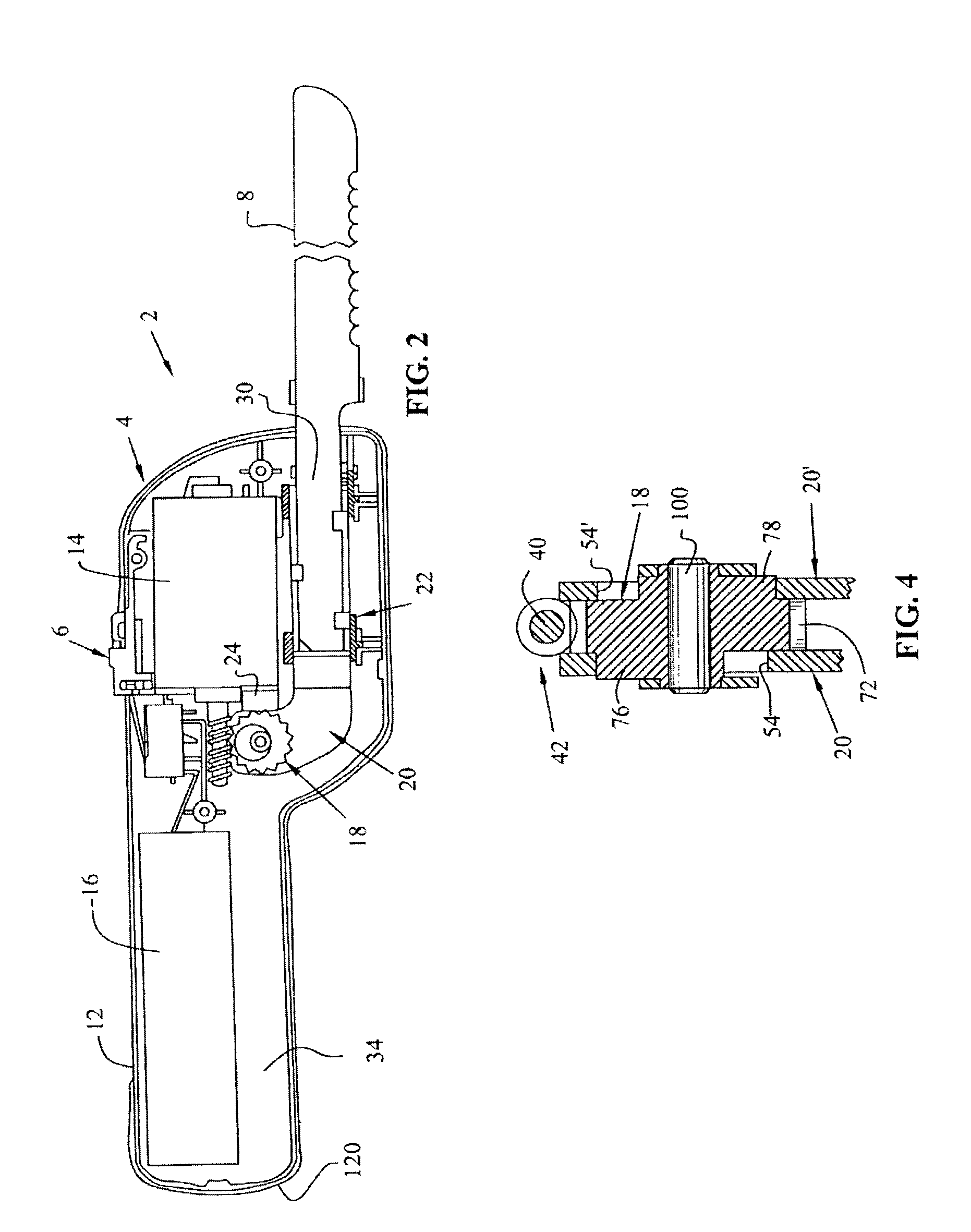
[0031]With reference first to FIG. 1, a battery-powered carving knife is shown generally at reference numeral 2 which includes a housing member 4 having a power switch at 6 to provide power to reciprocating knife blades shown at 8. The housing 4 generally includes a front motor receiving section 10 and a handgrip section at 12. With respect to FIG. 2, the carving knife 2 further generally comprises a motor at 14, driven by battery pack 16, which, as mentioned before, has intermediate power switch 6 for engaging or disengaging the motor 14. In the preferred embodiment of the invention, battery pack 16 is a nickel metal hydride (Ni—MH) battery pack; six batteries total, with three stacks of two batteries and is described in greater detail herein below. The carving knife 2 further includes a cam member 18, and reciprocating blade mounts at 20 which reciprocate within guide members 22. Cam 18 is held in place about a rotational axis by a bracket 24.

[0032]With reference now to FIGS. 1 an...


PUM

PropertyMeasurementUnit
Angleaaaaaaaaaa
Electric potential / voltageaaaaaaaaaa
aaaaaaaaaa

Abstract

A battery-powered carving knife is shown having a housing and a switch, which connects and disconnects a battery to a motor. A drive mechanism including a worm gear together with a cam member causes reciprocation of reciprocating blade mounts to reciprocate back and forth in an out of phase fashion. The motor is positioned forward within the housing in motor receiving section, with the drive shaft of the motor facing rearwardly. The blade mounts are driven by the motor, and reciprocate in a position below the motor. The motor and blade mounts are positioned in front of a handgrip section, thereby improving the ergonomics of the device. Alternatively, the drive shaft can be positioned facing forward.

Description

[0001]This application claims the benefit of U.S. patent application Ser. No. 10 / 122,887 filed Apr. 15, 2002, as a continuation-in-part.BACKGROUND OF THE INVENTION[0002]The invention relates to a battery-powered knife having reciprocating blades for carving or cutting.[0003]It is well known in the industry of carving knives to include either electrically or battery-powered carving knives. Typically these carving knives include a housing or casing to house the motor, and include a drive mechanism which includes means for driving a pair of carving knife blades in a reciprocating manner such that the knives are 180° out of phase. This back and forth reciprocation of the blades assists in the carving process. Such carving knives are typically used for home use for carving of meats of various sorts, but such knives can also be used for cleaning and preparation of fish. One of the drawbacks to existing products, whether electrically driven or battery-powered, is that the motor is located ...

Claims


Application Information

Patent Timeline
IPC IPC(8): A22C17/00B23D49/00B23D51/16B26B7/00
CPCA22C17/0013B23D49/006B23D51/16B26B7/005
Inventor WONG, STEVE
Owner KDW COMPANY
Learn More