Loading device for non-destructive inspections of composite structures

a composite structure and loading device technology, applied in the direction of measurement devices, structural/machine measurement, instruments, etc., can solve the problems of general unsuitability of composite structure methods, limited methods to structures that include ferromagnetic, and internal defects of non-destructive inspection instruments that become more apparent to non-destructive inspection instruments, etc., to achieve the effect of improving the results of non-destructive inspection and accentuating internal defects in the structur

Active Publication Date: 2005-12-20
THE BOEING CO
View PDF7 Cites 11 Cited by
  • Summary
  • Abstract
  • Description
  • Claims
  • Application Information

AI Technical Summary

Benefits of technology

[0011]The invention addresses the above needs and achieves other advantages by providing a loading device for applying a load, such as a normal load, to a structure during a non-destructive inspection of the structure. The loading device comprises a load indicator to indicate the load applied to the structure and may further comprise a connector attached to the load indicator for connecting the load indicator to the surface of the structure being inspected. The loading device also comprises a support for supporting the load indicator and connector. The support contacts a surface of the structure proximate the area of the structure to be inspected. A load applicator in mechanical communication with the connector, the load indicator, and / or the structure applies the load to the structure. The load improves the results of the non-destructive inspection by accentuating some internal defects in the structure.

Problems solved by technology

Certain internal flaws are more readily detectable when the structure being inspected is loaded so that the internal flaws become more apparent to the non-destructive inspection instruments.
These internal flaws may include weak bonds that will separate when loaded or may include incomplete bonds between layers that contact one another when experiencing no load but that also readily separate once loaded.
One destructive method of applying a load is to adhesively bond a button or other feature to a surface of the structure and cutting a portion of the structure around the adhered button.
Such methods are limited to structures that include ferromagnetic materials since a magnet is needed to engage the structure.
Unfortunately, this method is generally unsuitable for composite structures since many composites do not comprise ferromagnetic materials.
Such vacuum stress systems require a relatively large suction area, which may limit access to the surface of the structure requiring inspection.
In addition, such vacuum stress systems are not able to create a suction on a surface that defines protrusions because such protrusions would compromise the seal of the suction.

Method used


Image

  • Loading device for non-destructive inspections of composite structures
  • Loading device for non-destructive inspections of composite structures
  • Loading device for non-destructive inspections of composite structures

Examples


Embodiment Construction

[0021]The present invention now will be described more fully hereinafter with reference to the accompanying drawings, in which some, but not all embodiments of the invention are shown. Indeed, the invention may be embodied in many different forms and should not be construed as limited to the embodiments set forth herein; rather, these embodiments are provided so that this disclosure will satisfy applicable legal requirements. Like numbers refer to like elements throughout.

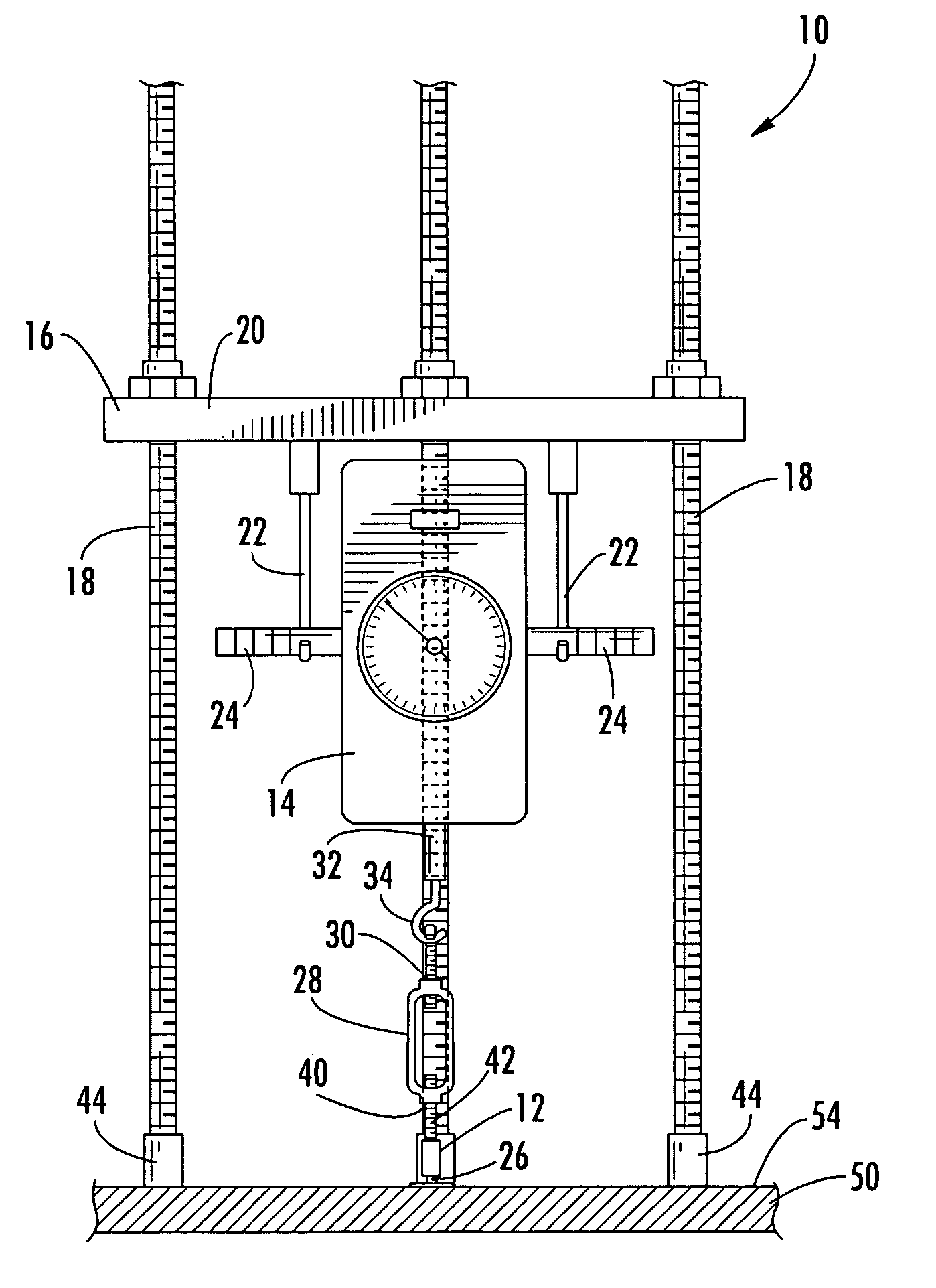
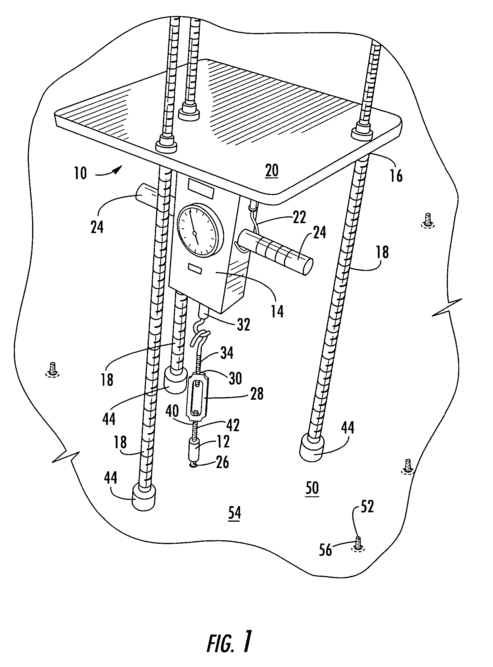
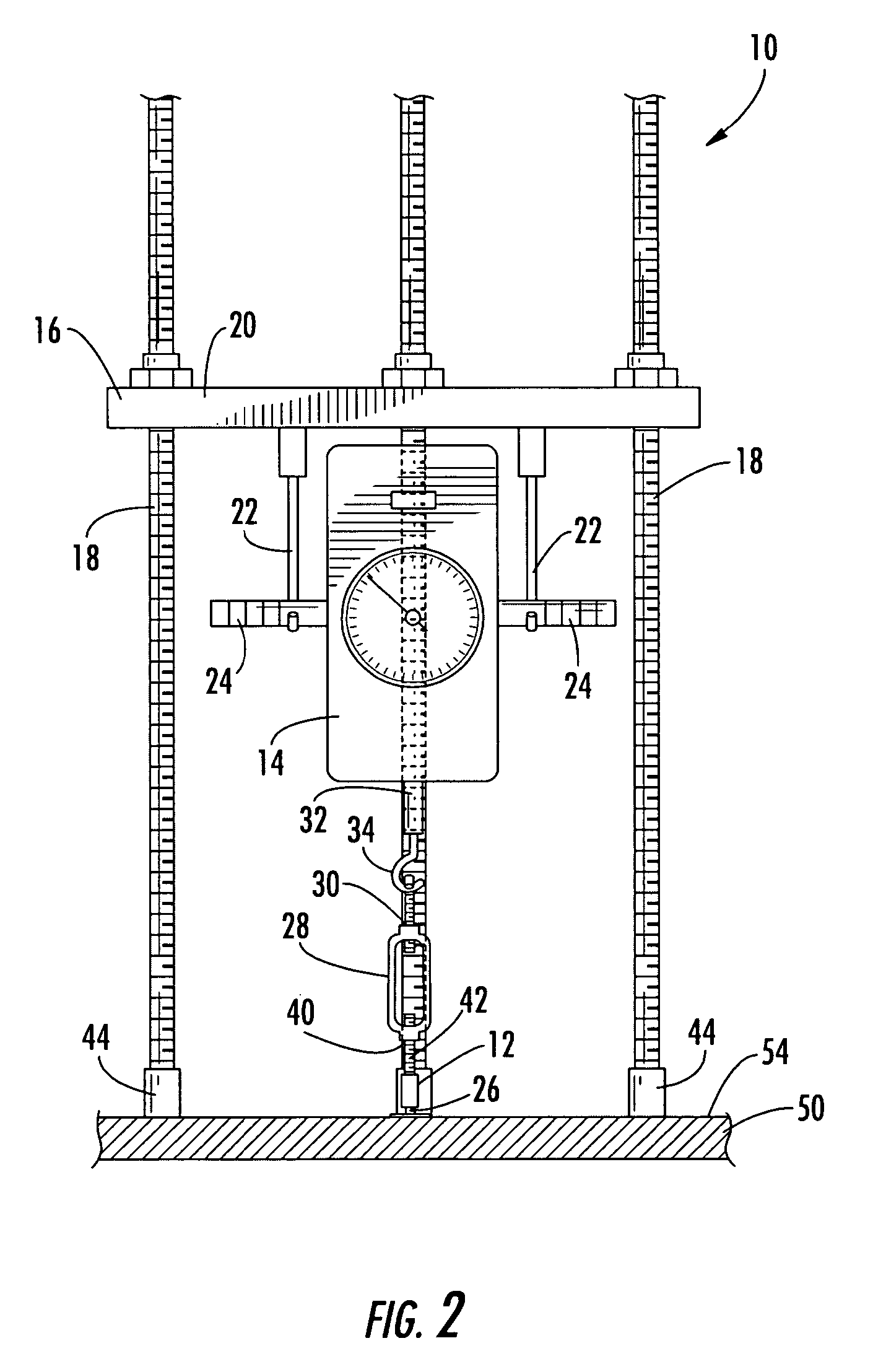
[0022]With reference to FIGS. 1–4, a loading device 10 in accordance with one embodiment of the present invention is illustrated. The loading device 10 applies a load to a surface of a composite structure during nondestructive inspections of an area of the structure. The load applied is advantageously a normal load as in the illustrated embodiment, though further embodiments may apply a load at any direction relative to the surface of the structure. The loading device 10 of the illustrated embodiment is typically u...


PUM

PropertyMeasurementUnit
distanceaaaaaaaaaa
areaaaaaaaaaaa
lengthaaaaaaaaaa

Abstract

There is provided a loading device for applying a load to a composite structure during a non-destructive inspection. The loading device comprises a load indicator to indicate the load applied, which is preferably a normal load, and comprises a connector attached to the load indicator to connect the loading device to a surface of the structure. A support contacts the structure to support the load indicator and the connector. The support preferably comprises a plate and three legs, wherein the load indicator is attached to the plate and the legs contact the structure. The legs may comprise protective ends for contacting the structure and may define adjustable lengths. A load applicator in mechanical communication with the connector and the load indicator applies the load to the structure, advantageously by reducing the distance between the connector and load indicator to create the load. The connector may connect to the surface of the structure defining a protrusion or to a protrusion removably adhered to the surface of the structure.

Description

BACKGROUND OF THE INVENTION[0001]1. Field of the Invention[0002]The present invention is related to non-destructive inspection equipment, and more particularly, to a loading device that applies a normal load to a composite structure being non-destructively inspected.[0003]2. Description of Related Art[0004]Non-destructive inspection of structures involves examining a structure without harming the structure or requiring significant disassembly of the structure. Non-destructive inspection is advantageous for many applications in which a thorough inspection of the exterior and / or interior of a structure is required. For example, non-destructive inspection is commonly utilized in the aircraft industry to inspect aircraft structures for any type of internal or external damage to the structure.[0005]Among the structures that are routinely non-destructively tested are composite structures. In this regard, composite structures are commonly used throughout industry because of their engineeri...

Claims


Application Information

Patent Timeline
Patent Type & Authority Patents(United States)
IPC IPC(8): G01M99/00G01N3/08G01N29/22
CPCG01N3/08G01N29/227G01N2291/0231G01N2291/02854G01N2291/0422
Inventor ROE, RICHARD D.SHAEFFER, CLIFFORD F.
Owner THE BOEING CO
Why Eureka
Try Eureka