
Manually operable standing wheelchair

a wheelchair and man-operable technology, applied in the direction of hand carts with one axis, wheelchairs/patient conveyances, transportation and packaging, etc., can solve the problem that the wheelchair may be dangerous for the occupant, and achieve the effect of increasing the wheelbase of the wheelchair, facilitating safe operation of the wheelchair, and ensuring safety

Inactive Publication Date: 2005-12-20
REHABILITATION INST OF CHICAGO
View PDF19 Cites 60 Cited by
  • Summary
  • Abstract
  • Description
  • Claims
  • Application Information

AI Technical Summary

Benefits of technology

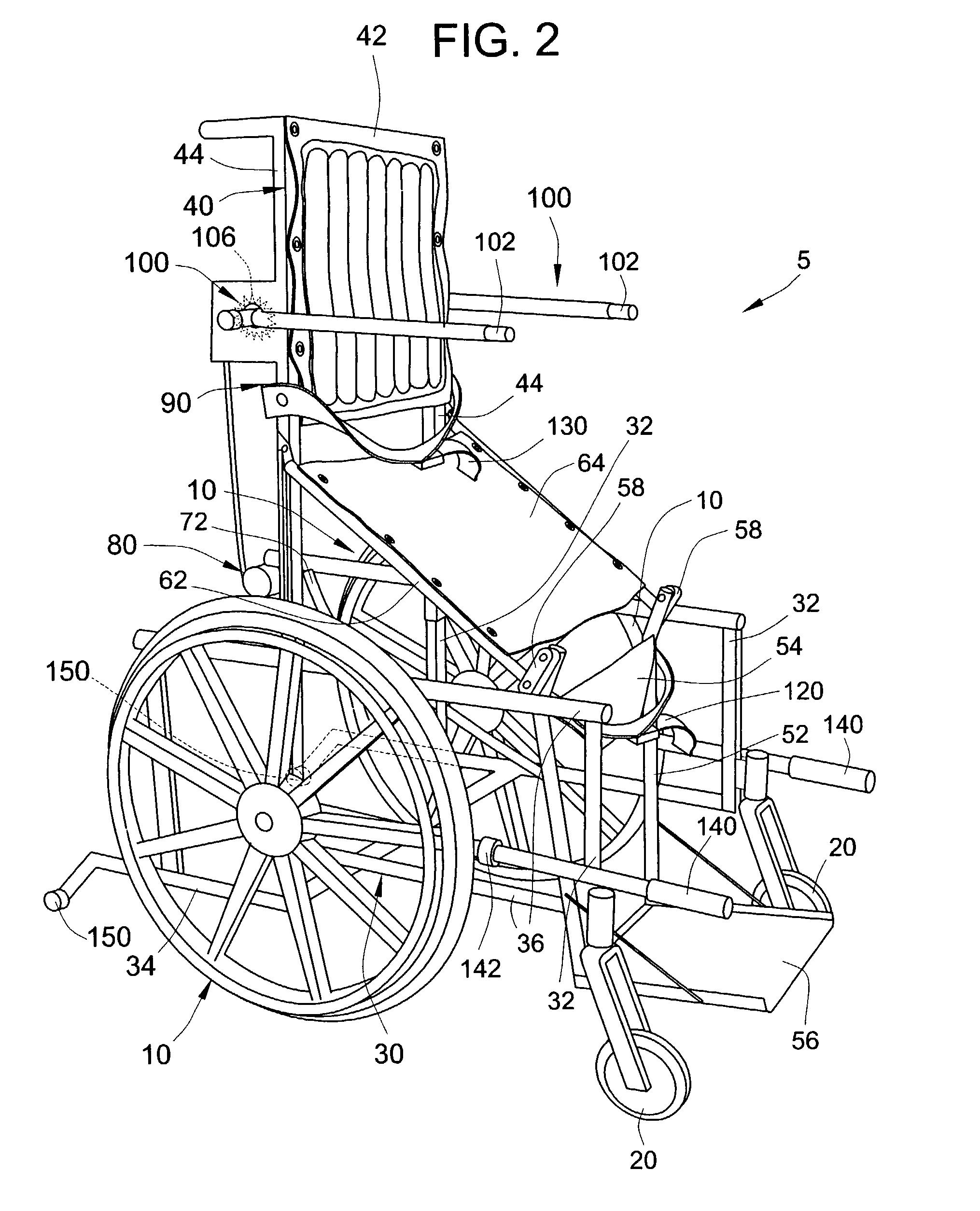
[0010]The standing operation is based on a support linkage system and telescoping tubes. The support system includes a chair back section with a pair of chair back tubes, which are hingably collected to a seat support linkage. The seat support linkage, in turn, is hingably connected to a leg rest. In moving from a sitting position to a standing position, the pair of chair back tubes telescope up a pair of generally vertical tubes included with a base portion for the wheelchair, and the chair back is thereby lifted. As the chair back is lifted, the seat support linkage is pulled up and back. The end result is that the occupant is lifted up and back into a standing position in the middle of the base portion for the wheelchair. The occupant is secured to the standing wheelchair at the knees and above the waist to prevent falling out of the chair while standing and to maintain correct posture in the standing position.
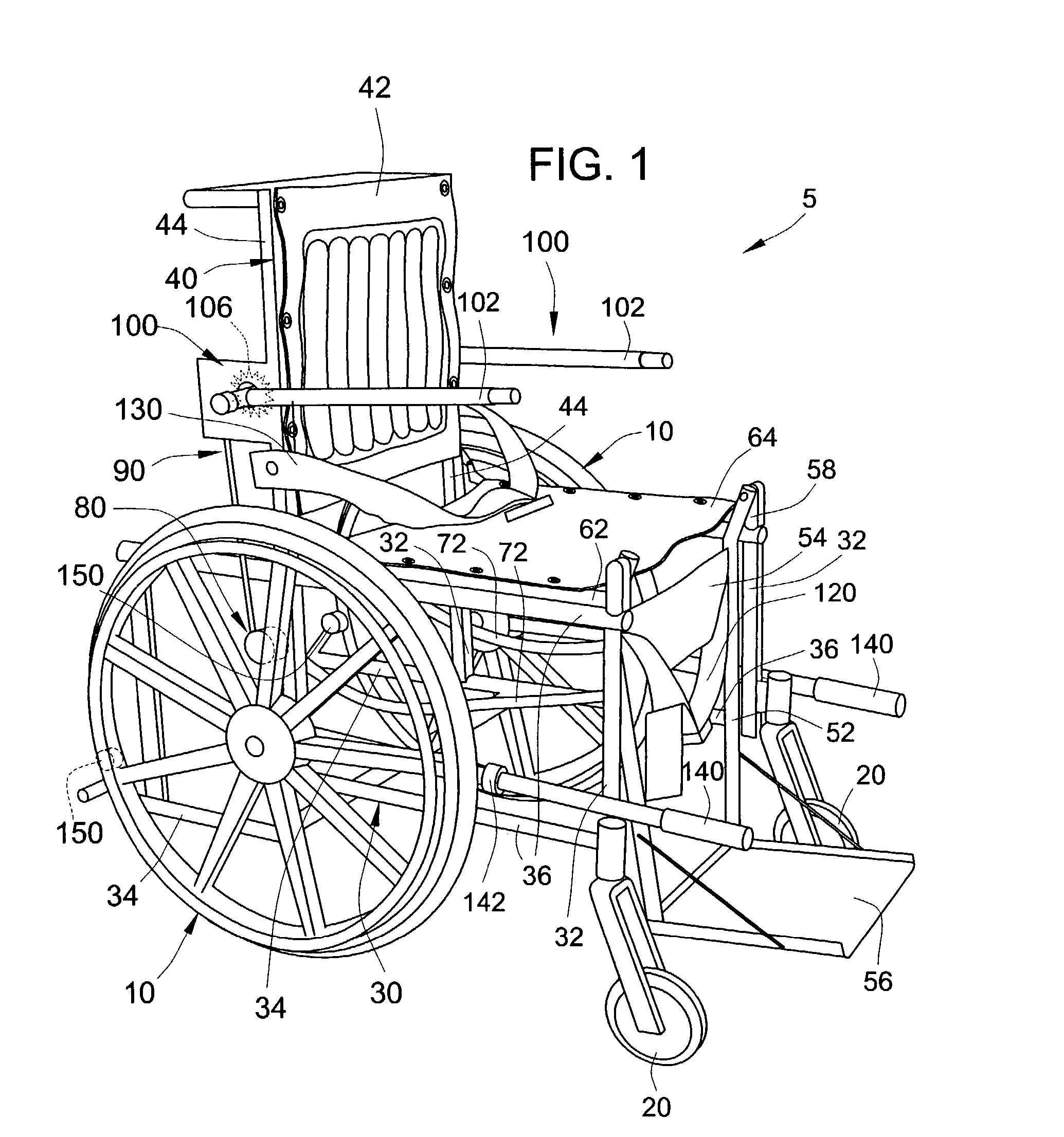
[0012]In an embodiment of the present invention, as soon as the seat is lifted a few inches, a spring-loaded mechanism deploys a pair of anti-tip wheels. The anti-tips wheels extend the wheelbase of the wheelchair, providing a more stable platform for safe operation of the wheelchair on smooth, level surfaces. With the pair of anti-tip wheels deployed, the wheelchair has six wheels in contact with the ground: a pair of drive wheels, a pair of front wheels, and the pair of anti-tip wheels. Advantageously, this plurality of wheels prevents the operation of the wheelchair on inclines or rough terrain, where the wheelchair may be dangerous for use by an occupant.
[0013]When the chair back is fully raised, the occupant is pulled up and back within the wheelbase, and between a pair of generally horizontal tubes included with the base portion into an erect, standing position. The lever arms, which also serve as armrests, can be rotated out of the way. Because of the high center of gravity, it is not prudent to move the wheelchair in the standing position on inclined or rough surfaces. However, remaining stationary in the standing position on a rough surface can be done safely.
[0014]In an embodiment, it is necessary to use a lever drive system for moving the wheelchair, since the occupant may not be able to reach the pair of drive wheels while in the standing position. Lever drive systems have the advantage of greater ergonomic efficiency. The lever drive system includes a pair of lever drive arms that pivot about a pair of rear drive wheels, each of the pair of lever drive arms having friction pads mounted at the lever of the tires. Pressing the friction pads into the tires of the pair of drive wheels and stroking with a rowing-type motion effectively rotates the pair of drive wheels, moving the wheelchair. The length of the pair of lever arms is adjustable so that the wheelchair is conveniently and efficiently movable from both the sitting position and the standing position.
[0025]In an embodiment, the present invention may also comprise at least one adjustable drive lever. Adjustable drive levers include a first end pivotally mounted to the base frame and a second end opposite the first end that is capable of being gripped by an occupant in a standing position. By a lateral movement of the adjustable drive levers, the occupant may selectively contact at least one of the plurality of wheels, for example, either the left or right drive wheel, so that pivotal motion of the adjustable drive levers may cause rotation of the left or right drive wheel. Optionally, the adjustable drive levers may also include a friction pad positioned to contact the left or right drive wheel. The friction pads merely make the use of the adjustable drive levers more convenient by improving the selective contact between the adjustable drive levers and the wheels. Also optionally, the base frame portion may have a drive lever stop projecting outwardly from one or more of the generally horizontal tubes of the base frame portion. The drive lever stop prevents the drive levers from being pivotally rotated out of reach of an occupant of the adjustable frame.

Problems solved by technology

Advantageously, this plurality of wheels prevents the operation of the wheelchair on inclines or rough terrain, where the wheelchair may be dangerous for use by an occupant.

Method used


Image

  • Manually operable standing wheelchair
  • Manually operable standing wheelchair
  • Manually operable standing wheelchair

Examples


Embodiment Construction

[0037]There are some disabled people who, notwithstanding an incapacity to move their legs while walking, have an ability to support the weight of their upper body with their lower body. The manually operable standing wheelchair of the present invention is a mechanical device that allows an occupant, such as a paraplegic, to move under their own power from a sitting position to standing position. The present invention also allows for the occupant to move the wheelchair around while in the sitting position, the standing position, or in any position in between.

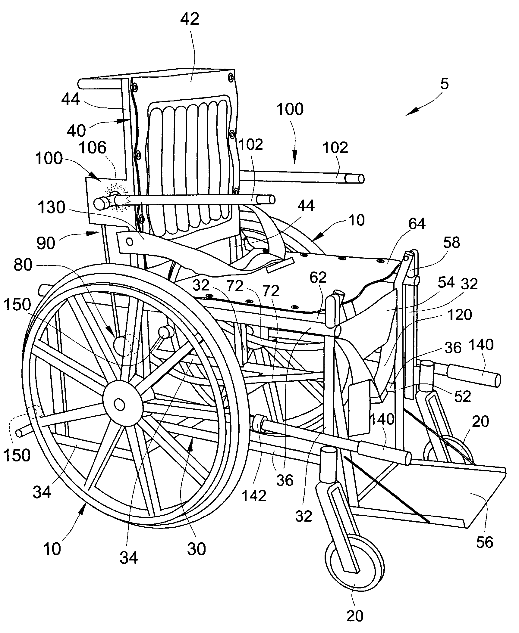
[0038]The embodiment of the manually operable standing wheelchair labeled 5 in the drawings includes a base frame portion 30, chair back portion 40, support linkages 62 and 72, and a plurality of wheels. The base frame portion 30 has vertical tubes 32, horizontal tubes 36, and a pivotal mount 34 for an anti-tip wheel 150. In order to accommodate an occupant, a seat back 42 is mounted to chair back tubes 44, and a seat bottom 64 ...


PUM


Abstract

A manually operable standing wheelchair includes an actuator for moving an occupant from a sitting position to a standing position. The manually operable standing wheelchair has a lifting mechanism, including, for example, a ratchet, cable, pulley, and telescopic tubes, which the occupant may manually operate to shift from the sitting position to the standing position. There is also a drive system to enable the occupant to manually move himself or herself in and the wheelchair from the sitting position to the standing position, or in any position in between. For example, the drive system may include adjustable lever drive arms with friction pads adapted for allowing the occupant to move in any position. In an embodiment, the wheelchair is equipped with a set of spring loaded anti-tip wheels that automatically deploy when the manual wheelchair begins to lift from the sitting position to the standing position.

Description

FIELD OF THE INVENTION[0001]This invention pertains to manually operable mechanical devices for moving a person. Specially, the invention pertains to a wheelchair that allows an occupant to adjust the wheelchair from a sitting position to a standing position, and to manually move around.BACKGROUND OF THE INVENTION[0002]An image of a chair with wheels is inscribed into a sarcophagus in China, with the date of the inscription estimated to be around the sixth century, A.D. Wheelchairs did not become common, however, until the late 19th century.[0003]U.S. Pat. No. 531,330 to Sarah A. Potter (“the Potter patent”) shows an example of an early patent for the modern wheelchair. The wheelchair provides a seat back, seat bottom, and footrest. An occupant may rest in the wheelchair in a sitting position. The seat back, seat bottom and footrest are part of a mechanical frame for the wheelchair. Also attached to the frame are two sets of wheels, one smaller set in front (“the front wheels”), and...

Claims


Application Information

Patent Timeline
Patent Type & Authority Patents(United States)
IPC IPC(8): A61G5/14
CPCA61G5/14A61G2005/1054A61G2200/36A61G5/1054
Inventor KUIKEN, TODD A.
Owner REHABILITATION INST OF CHICAGO
Learn More