Peritoneal dialysis catheters

a peritoneal dialysis and catheter technology, applied in the field of catheters, can solve the problems that the patient's manual peritoneal dialysis requires quite a lot of time and effort, and achieve the effects of enhancing dialysate mixing, minimizing shunting, and enhancing dialysate mixing

Inactive Publication Date: 2005-12-20
BAXTER INT INC
View PDF116 Cites 111 Cited by
  • Summary
  • Abstract
  • Description
  • Claims
  • Application Information

AI Technical Summary

Benefits of technology

[0010]The new catheter delivers fresh dialysate into the peritoneal cavity at a location significantly separated from a location at which the catheter removes spent dialysate from the peritoneal cavity. The separation of the patient inflow and outflow locations of the catheter tends to enhance mixing of the dialysate within the peritoneal cavity. Also, as the dialysate flows from the patient inflow location through the peritoneal cavity to the patient outflow location, the dialysate may tend to contact a relatively large area of the peritoneal membrane. A situation in which the dialysate flows directly from the patient inflow location to the patient outflow location on the catheter with minimal contact of the peritoneal membrane, shunting, tends to be avoided. At the patient inflow location, the catheter has fluid openings from the inflow lumen which are directed away from the fluid openings to the patient outflow lumen at the patient outflow location. This direction of the patient inflow fluid openings also tends to enhance dialysate mixing and minimize shunting within the peritoneal cavity.
[0011]One catheter according to the present invention extends from a proximal end outside of the patient, upward into the patient and to a preformed bend. The proximal end has openings to the patient inflow and outflow lumens for connection to a dialysis machine, including a dialysate supply and drain. The patient inflow lumen extends from the proximal end to a patient inflow port at the preformed bend. The catheter continues to extend downward from the preformed bend to a distal end inside of the patient's peritoneal cavity. The patient outflow lumen extends from the proximal end to a patient outflow port at the distal end. The distal end of the catheter may have a coiled shape. As implanted into the patient, the preformed bend is positioned in the upper area of the peritoneal cavity and the coiled distal end is positioned in the lower area of the peritoneal cavity. CT Scan and MRI imaging of normal peritoneal dialysis patients lying in supine position (on back) with fluid filled peritoneal cavities shows two distinct pools of fluid. One pool is found in the upper region of the cavity in the vicinity of the liver and spleen. The second pool is located in the lower pelvic region separated from the upper pool by the intestinal mass. This catheter shape was conceived to take advantage of this reality by locating the patient in flow section in the upper pool where fresh dialysate is infused directly. Once infused, the fresh dialysate is forced to filter down through the intestinal mass to the patient outflow section strategically located in the lower pool. This process enhances mixing with spent dialysate and exposes a large area of the peritoneal membrane to “fresher” dialysate for improved toxin and water removal. The catheter shape also assists in maintaining the catheter position within the peritoneal cavity, i.e., the patient inflow preformed bend positioned high in the peritoneum and the patient outflow end positioned low in the peritoneum. This can help reduce or prevent omental adhesion to the catheter due to catheter tip migration which causes catheter fluid flow obstructions.

Problems solved by technology

Manual peritoneal dialysis performed by the patient requires quite a lot of time and effort by the patient.

Method used


Image

  • Peritoneal dialysis catheters
  • Peritoneal dialysis catheters
  • Peritoneal dialysis catheters

Examples


Embodiment Construction

[0036]Although the present invention can be made in many different forms, the presently preferred embodiments are described in this disclosure and shown in the attached drawings. This disclosure exemplifies the principles of the present invention and does not limit the broad aspects of the invention only to the illustrated embodiments.

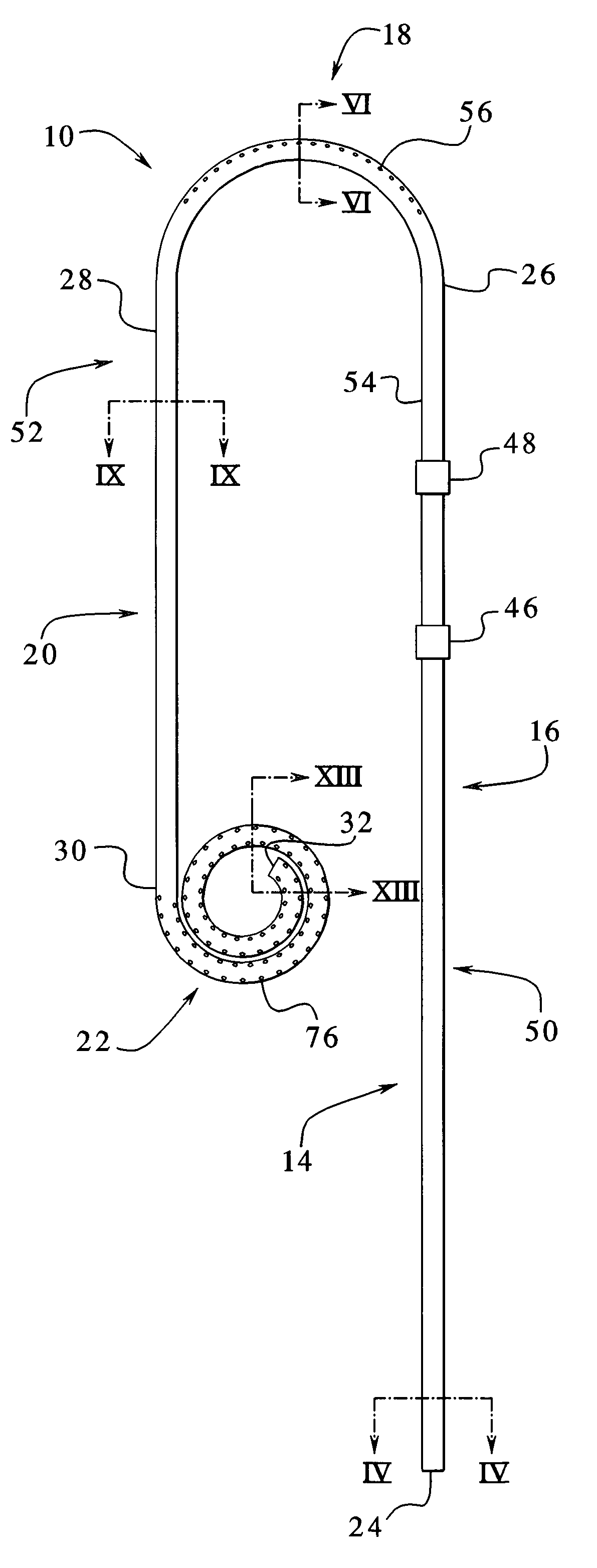
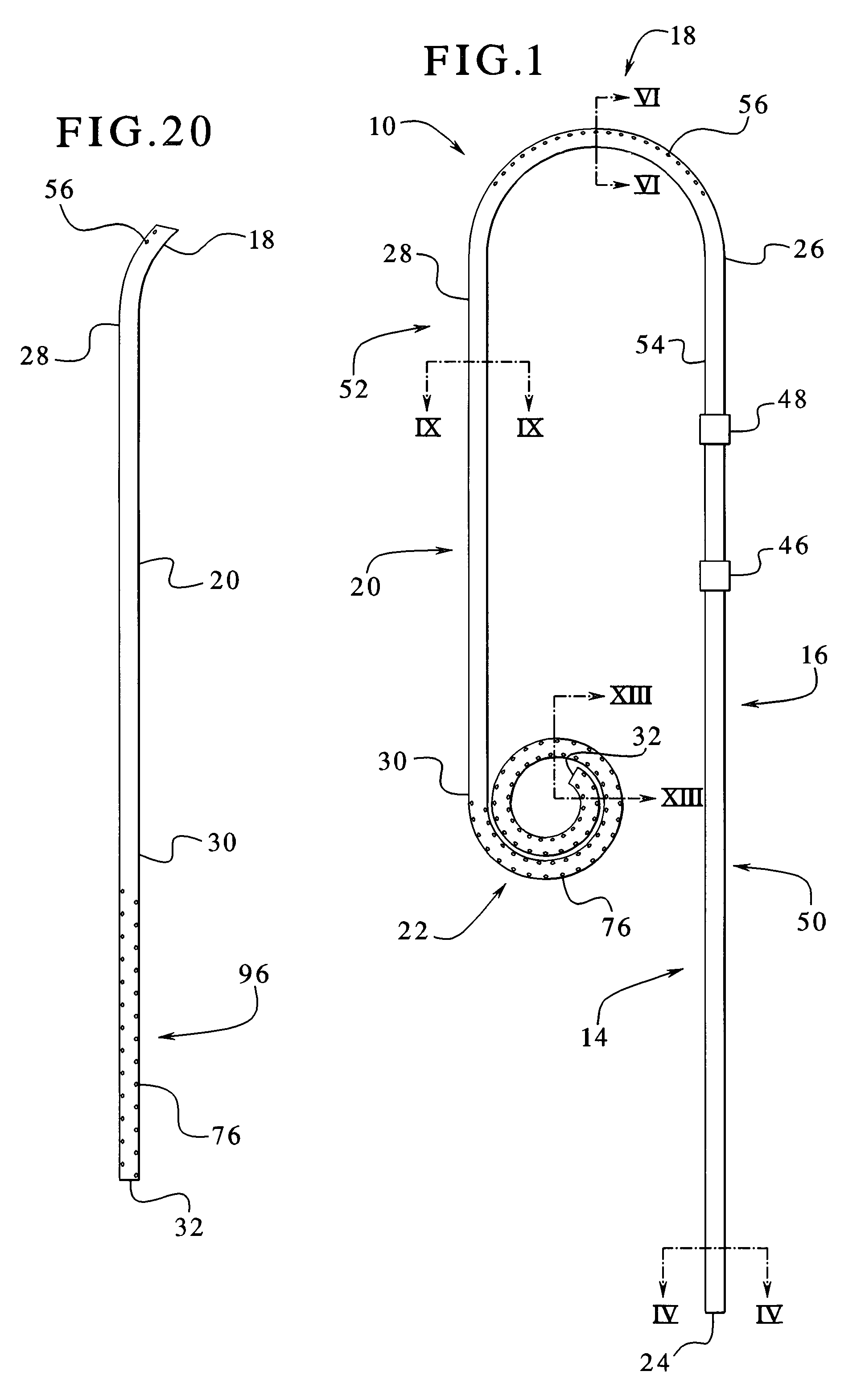
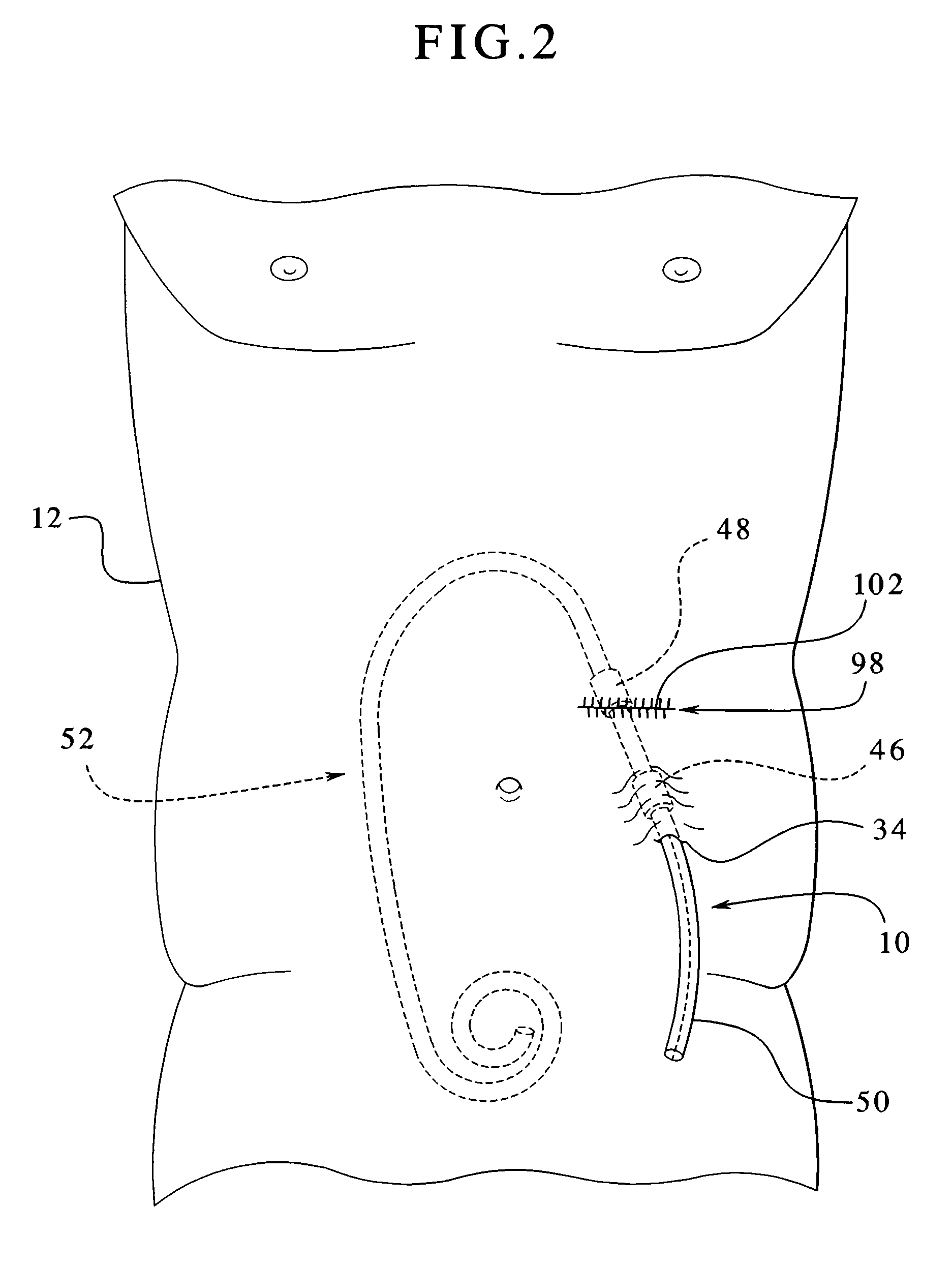
[0037]A new catheter 10 according to the principles of the present invention is shown by way of example in FIG. 1. The catheter 10 is implanted into a patient's peritoneal cavity for peritoneal dialysis. Referring also to FIG. 2, the catheter 10 is shown partially in phantom implanted into a patient 12. The catheter 10 allows for dialysate to be infused into and removed out of the peritoneal cavity. Particularly, the catheter 10 allows for continuous flow peritoneal dialysis treatment. Again, continuous flow peritoneal dialysis means that dialysate flows simultaneously into and out of the peritoneal cavity. The catheter 10 can also be used to perform o...


PUM


Abstract

A catheter suitable for use in performing peritoneal dialysis. The catheter is a dual lumen catheter which allows for continuous flow peritoneal dialysis. Dialysate flows through the catheter into the patient via one lumen and simultaneously flows through the catheter out of the patient via the second lumen. The dual lumen dialysis catheter has a flexible tube which has an implantable portion extending from an external patient portion. Both of the lumens have openings in the external patient portion for connecting to a supply and drain of dialysate, respectively. The implantable portion has a preformed curved segment which has an outlet for the first lumen to flow dialysate into the patient's peritoneal cavity. The implantable portion has an opening for the second lumen at the distal end to flow dialysate out of the peritoneal cavity and removal from the patient. The catheter facilitates mixing of fresh and spent dialysate inside the peritoneal cavity by inflowing fresh dialysate into the cavity at a location substantially separated from the cavity outflow location, and by directing the inflow of dialysate into the cavity opposite the cavity outflow location.

Description

FIELD OF THE INVENTION[0001]The present invention generally relates to catheters, and more specifically, the present invention relates to dual lumen catheters having two fluid flow paths. The catheters can be used for peritoneal dialysis to infuse and remove dialysate simultaneously into and from a patient. The present invention also relates to methods of implanting and using catheters.BACKGROUND OF THE INVENTION[0002]Kidney failure and reduced kidney function have been treated with dialysis. Dialysis removes waste, toxins, and excess water from the body that would otherwise have been removed by normal functioning kidneys. Dialysis treatment for replacement of kidney functions is critical to many people because the treatment is life saving. One who has failed kidneys could not continue to live without replacing at least the filtration functions of the kidneys.[0003]Hemodialysis and peritoneal dialysis are two types of dialysis commonly used to treat loss of kidney function. Hemodial...

Claims


Application Information

Patent Timeline
Patent Type & Authority Patents(United States)
IPC IPC(8): A61M1/28
CPCA61M1/285A61M1/284A61M25/0041A61M2025/0293A61M25/00
Inventor RUDDELL, SCOTT A.YARDIMCI, ATIFCASTILLO, JORGE DEL
Owner BAXTER INT INC
Why Eureka
Try Eureka