Apparatus for and method of detecting defocus error signal for optical pickup and apparatus for and method of detecting seek direction

a technology of optical pickups and error signals, applied in the field of apparatus for and detecting defocus error signals for optical pickups, can solve problems such as small defocus amoun

Inactive Publication Date: 2005-12-20
SAMSUNG ELECTRONICS CO LTD
View PDF9 Cites 1 Cited by
  • Summary
  • Abstract
  • Description
  • Claims
  • Application Information

AI Technical Summary

Benefits of technology

[0011]To satisfy the above needs, it is an object of the present invention to provide an apparatus for and method of accurately detecting a defocus error signal which is minimally affected by a tilt of a recording medium, detrack, and a shift of an objective lens.

Problems solved by technology

Accordingly, a small amount of defocus may be a problem in recording.

Method used


Image

  • Apparatus for and method of detecting defocus error signal for optical pickup and apparatus for and method of detecting seek direction
  • Apparatus for and method of detecting defocus error signal for optical pickup and apparatus for and method of detecting seek direction
  • Apparatus for and method of detecting defocus error signal for optical pickup and apparatus for and method of detecting seek direction

Examples


Embodiment Construction

[0036]Reference will now be made in detail to the present embodiments of the present invention, examples of which are illustrated in the accompanying drawings, wherein like reference numerals refer to like elements throughout.

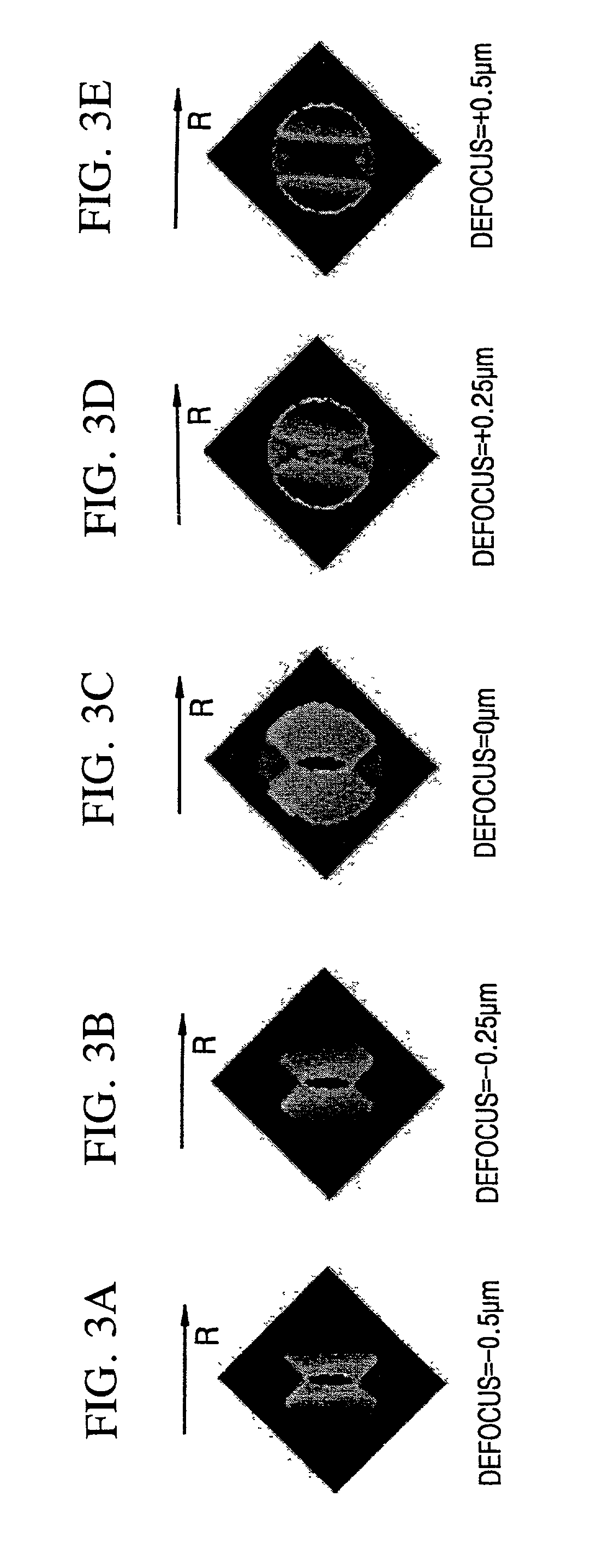
[0037]FIGS. 3A through 3E show distributions of intensity of light spots having a 400 nm wavelength (λ) according to an amount of defocus where the light spots are formed by using an objective lens having a 0.65 NA on a land / groove type next generation DVD-RAM disc having a track pitch of 0.34 μm and a groove depth of λ / 6. In FIGS. 3A through 3E, the horizontal direction and the vertical direction signify a radial direction and a tangential direction of a recording medium, respectively. As shown in FIGS. 3A through 3B, light spot intensity varies between a central portion and a peripheral portion of the light spot in a radial direction on a next generation DVD-RAM disc according to the amount of defocus. The intensity variation is approximately opposite with re...


PUM

PropertyMeasurementUnit
lengthaaaaaaaaaa
spot sizeaaaaaaaaaa
spot sizeaaaaaaaaaa

Abstract

An apparatus for and a method of detecting a defocus error signal. First, second and third light receiving regions of a photodetector are arranged in a radial direction of a recording medium to independently perform photoelectric conversion with respect to incident light which is reflected/diffracted by the recording medium. A subtractor subtracts a sum signal of detection signals from the first and third light receiving regions and a detection signal of the second light receiving region to output a defocus error signal, to detect defocus and/or a change in thickness of the recording medium. The defocus error signal and a push-pull tracking error signal are compared in a state in which a predetermined amount of defocus is applied to a light spot to detect a seek direction of the recording medium having a land/groove structure.

Description

CROSS-REFERENCE TO RELATED APPLICATIONS[0001]This application claims the benefit of Korean Application No. 2000-60030 filed Oct. 12, 2000, in the Korean Patent Office, the disclosure of which is incorporated herein by reference.BACKGROUND OF THE INVENTION[0002]1. Field of the Invention[0003]The present invention relates to an apparatus for and a method of detecting a defocus error signal for an optical pickup and an apparatus for and a method of detecting a seek direction of a recording medium having a land / groove structure adopting the same.[0004]2. Description of the Related Art[0005]For a recording medium of a next generation DVD family, that is, a recording medium requiring higher density recording than a recording medium of a DVD family, where information is recorded by being defocused, an effect of defocusing is much greater than other existing recording media which use a red laser beam. Thus, a method of compensating for defocusing is needed.[0006]To accommodate high density ...

Claims


Application Information

Patent Timeline
Patent Type & Authority Patents(United States)
IPC IPC(8): G11B7/007G11B7/085G11B7/09G11B7/13G11B7/131
CPCG11B7/00718G11B7/08505G11B7/0901G11B7/0943G11B7/131G11B7/09
Inventor MA, BYUNG-INPARK, IN-SIKCHUNG, CHONG-SAMJEON, JIN-HOONDOH, TAE-YONGCHOI, BYOUNG-HO
Owner SAMSUNG ELECTRONICS CO LTD
Why Eureka
Try Eureka