
System and method for network tunneling utilizing micro-flow state information

Active Publication Date: 2005-12-20
SABLE NETWORKS
View PDF8 Cites 94 Cited by
  • Summary
  • Abstract
  • Description
  • Claims
  • Application Information

AI Technical Summary

Benefits of technology

[0019]The advantage of aggregate flow blocks of embodiments of present invention is the ability to provide a switch with the ability to combine flow state information with other information (e.g., LSP utilization), thereby providing a mechanism for the micro-flows associated with an aggregate flow block to all be processed in a similar manner (e.g., LSP statistics collection, LSP alteration, and LSP teardown) without introducing prohibitively time consuming and processor intensive tasks to the network system.
[0020]Without the ability to utilize aggregate flow blocks, processing large numbers of micro-flows would be prohibitively time consuming and processor intensive. The aggregate flow block avoids the need to search millions of flow blocks to identify flow blocks having certain micro-flow characteristics (e.g., QoS). Other aspects and advantages of the invention will become apparent from the following detailed description, taken in conjunction with the accompanying drawings, illustrating by way of example the principles of the invention.

Problems solved by technology

However, conventional MPLS networks generally do not maintain flow state information on each individual micro-flow within a particular LSP.
As such, Quality of Service (QoS) in the IP network typically cannot be adequately provided.
Such failure to provide QoS results in such problems as micro-flows within a tunnel (e.g., LSP) cannot have different QoS characteristics.
In addition, routers that have some type of a switching fabric also may have some difficulty switching a large tunnel (e.g., LSP) within their switching fabric because the tunnels may exceed the bandwidth (e.g., 2.5 Gbps) of internal fabric links, thereby precluding the router from switching a tunnel that is larger than that bandwidth (e.g., 2.5 Gbps).
However, policing millions of flow state data entries, one for each micro-flow, presents a prohibitively time consuming and processor intensive task in a conventional MPLS network domain.
For the above reasons, conventional MPLS systems generally do not maintain flow state information on a per micro-flow basis, and as a result, generally do not provide adequate QoS.

Method used


Image

  • System and method for network tunneling utilizing micro-flow state information
  • System and method for network tunneling utilizing micro-flow state information
  • System and method for network tunneling utilizing micro-flow state information

Examples


Embodiment Construction

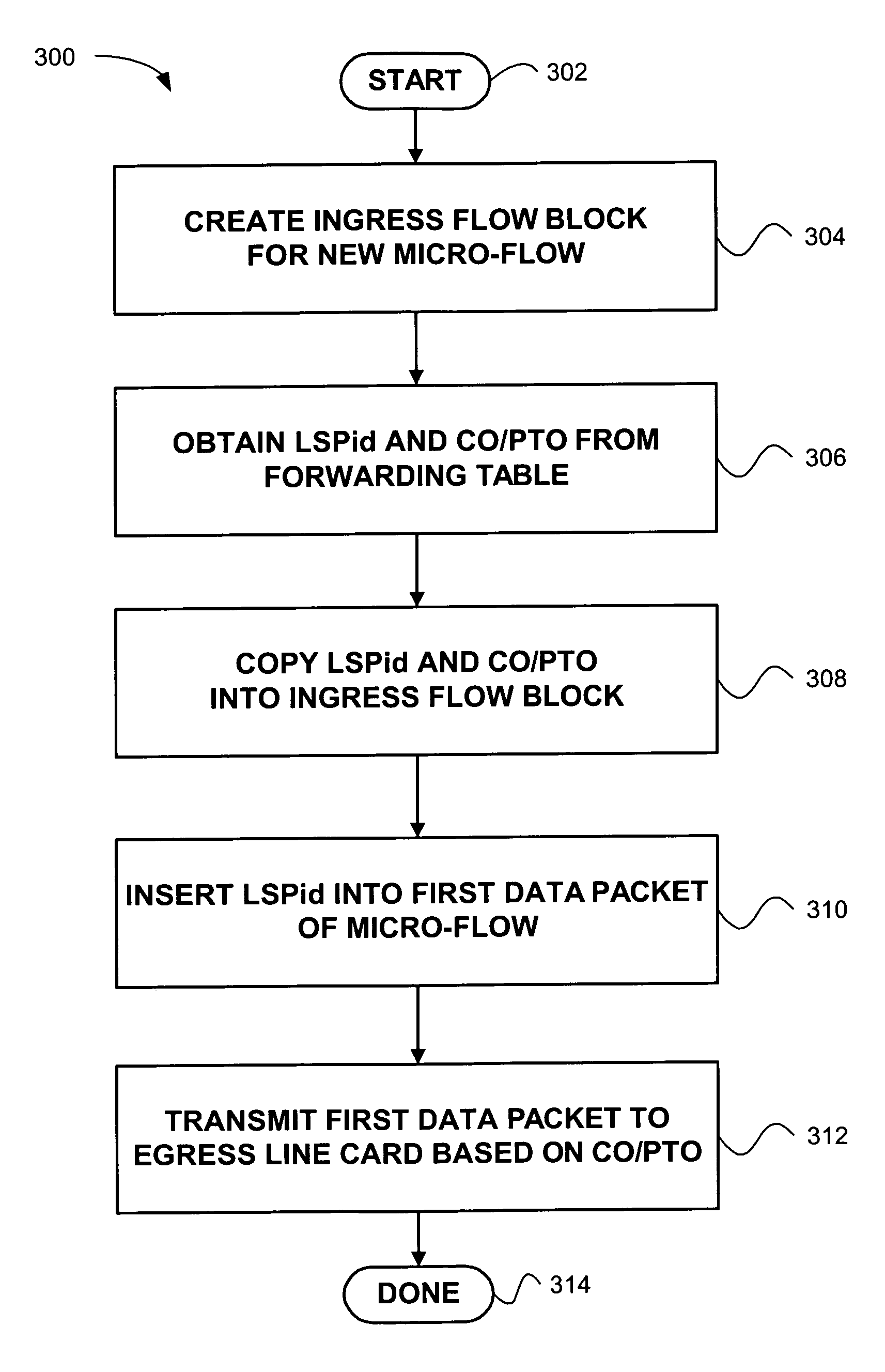
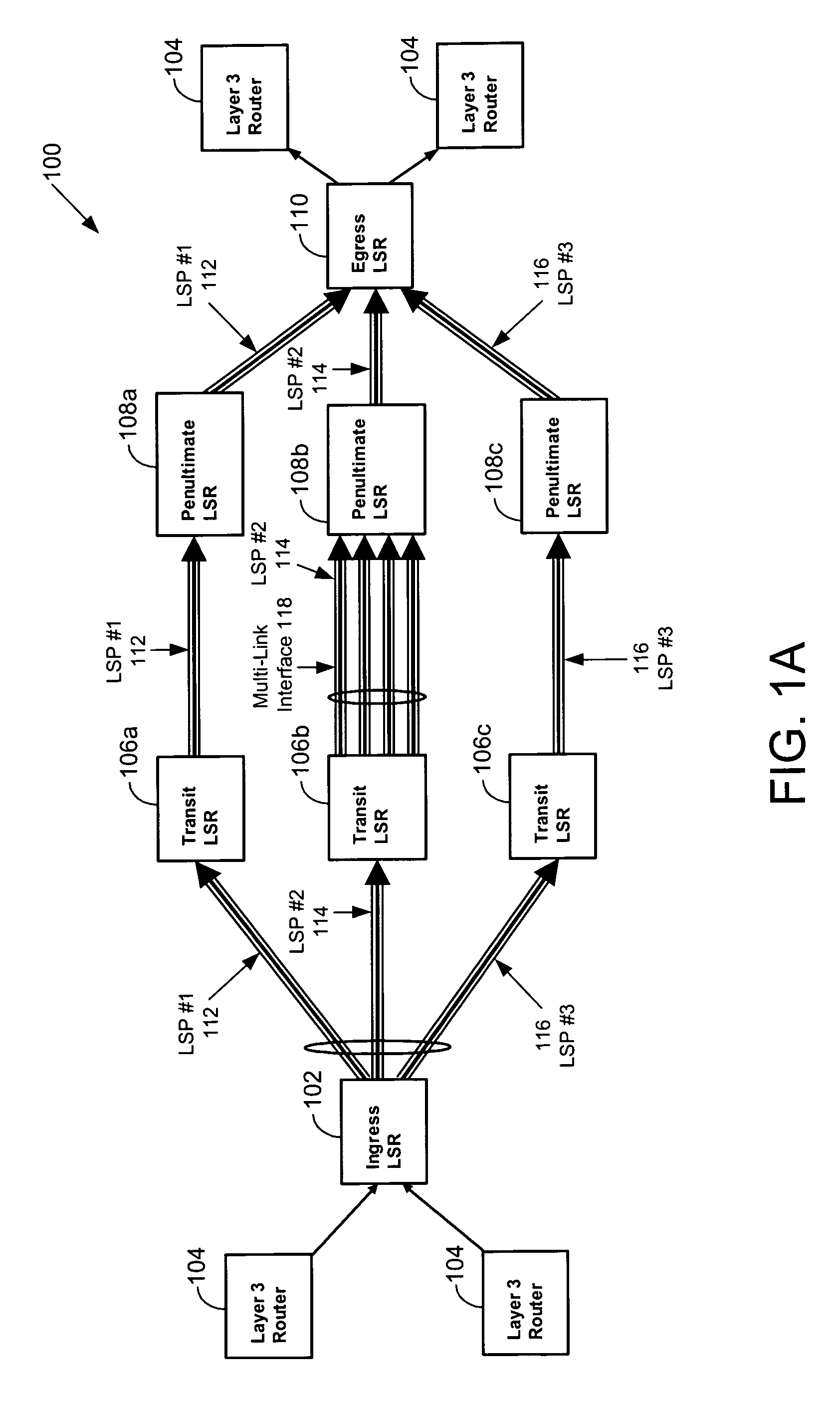
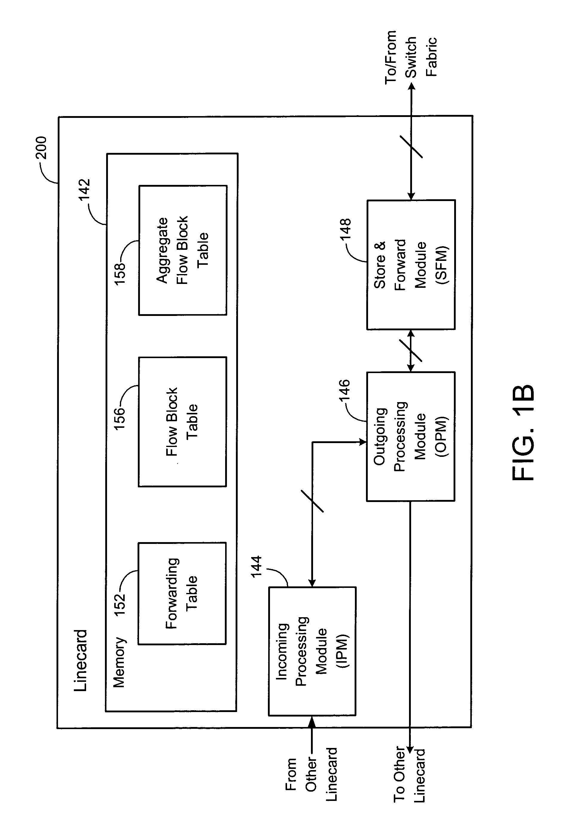
[0035]Embodiments of present invention are disclosed for a network tunneling system that maintains flow state information. In particular, the embodiments of the present invention utilize aggregate flow blocks, which maintain information (e.g., LSP information), in conjunction with flow blocks, which maintain flow state information for micro-flows (e.g., a uniquely identifiable set of data signals that typically have the same open system interconnection model network layer and transport layer characteristics, such as protocol type, source address, destination address, TCP / UDP source port number and TCP / UDP destination port number), to provide network tunneling based on state information.

[0036]In the following description, numerous specific details are set forth in order to provide a thorough understanding of various embodiments of the present invention. It will be apparent, however, to one skilled in the art that additional embodiments of the present invention may be practiced withou...


PUM


Abstract

Network tunneling methods and apparatus utilizing flow state information are provided. A router includes an ingress linecard having logic that selects a particular network tunnel for a received micro-flow. The ingress linecard further includes logic that selects a particular egress linecard and a particular port to utilize for transmitting the micro-flow. The router also includes an aggregate flow block that includes tunnel specific information for the selected network tunnel. The tunnel specific information includes but is not limited to label action and outgoing label(s), Layer 2 tunneling action or Layer 3 actions. The aggregate flow block further includes statistics for the selected network tunnel. In addition, the router includes a flow block having flow state information for the micro-flow. The flow block also includes an identifier that associates the flow block with the aggregate flow block.

Description

CROSS REFERENCE TO RELATED APPLICATIONS[0001]This application is related to U.S. patent application Ser. No. 09 / 552,278, filed on Apr. 19, 2000, entitled “MICRO-FLOW MANAGEMENT,” which is hereby incorporated by reference in its entirety. This application also is related to U.S. patent application Ser. No. 09 / 699,199, filed Oct. 27, 2000, entitled “SYSTEM AND METHOD FOR UTILIZATION BASED MICRO-FLOW LABEL SWITCHING,” which is hereby incorporated by reference in its entirety.BACKGROUND OF THE INVENTION[0002]1. Field of the Invention[0003]This invention relates generally to computer networking, and more particularly to methods and systems for using micro-flow state information in conjunction with network tunneling techniques.[0004]2. Description of the Related Art[0005]Due to high customer demand for increasingly reliable and differentiated services, today's Internet Service Providers (ISPs) are constantly faced with the challenge of adapting their networks to support increased customer...

Claims


Application Information

Patent Timeline
IPC IPC(8): G01R31/08H04J3/16H04L12/28H04L12/46H04L12/56H04L29/06
CPCH04L12/4633H04L45/24H04L45/38H04L45/50H04L47/12H04L69/14Y02B60/33Y02D30/50
Inventor HAUCK, SCOTT
Owner SABLE NETWORKS
Features
  • Generate Ideas
  • Intellectual Property
  • Life Sciences
  • Materials
  • Tech Scout
  • Unparalleled Data Quality
  • Higher Quality Content
  • 60% Fewer Hallucinations
Learn More