Complex filtering/AGC radio receiver architecture for low-IF or zero-IF

a radio receiver and complex filtering technology, applied in the field of circuitry for filtering and amplifying signals, can solve problems such as demodulator circuits and performance degradation, and achieve the effect of low power consumption and low power consumption

Inactive Publication Date: 2005-12-20
SKYWORKS SOLUTIONS INC
View PDF6 Cites 57 Cited by
  • Summary
  • Abstract
  • Description
  • Claims
  • Application Information

AI Technical Summary

Benefits of technology

[0008]The present invention is particularly advantageous in that the apparatus is capable of providing an overall output signal at a predetermined amplitude level within a restricted dynamic range from input signals having a wide variety of signal s...

Problems solved by technology

If real filters are used in a LIF path they have the disadvantage of not differentiating between negative frequencies and positive frequencies, hence a high performance image reject mixer is typically used to separate the positive/negative frequencies.
In additio...

Method used


Image

  • Complex filtering/AGC radio receiver architecture for low-IF or zero-IF
  • Complex filtering/AGC radio receiver architecture for low-IF or zero-IF
  • Complex filtering/AGC radio receiver architecture for low-IF or zero-IF

Examples


Embodiment Construction

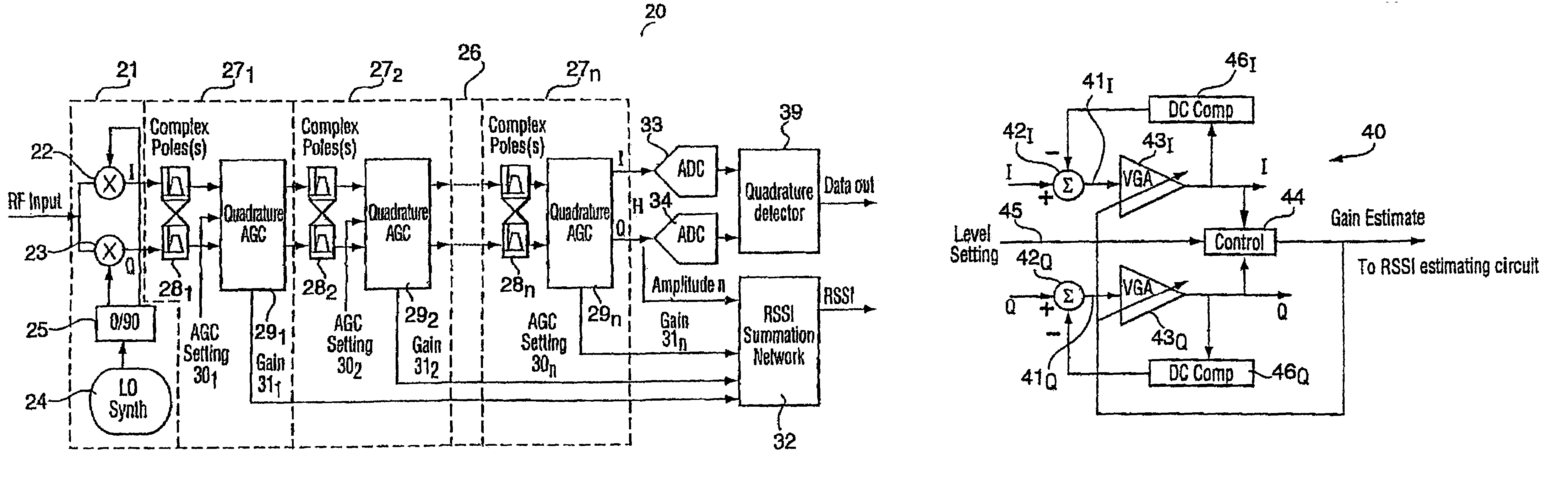
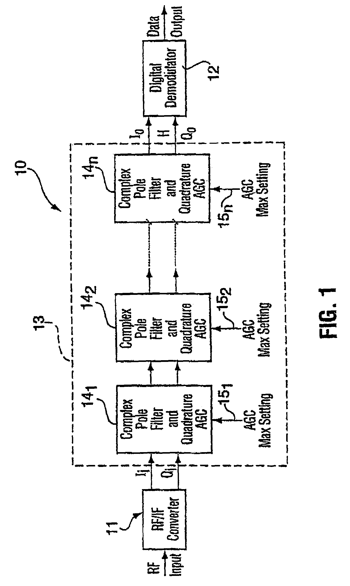
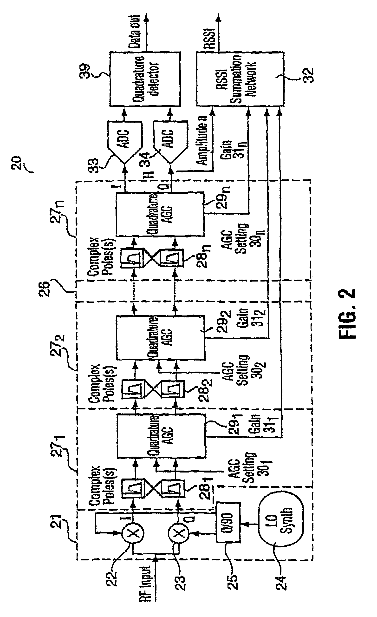
[0023]Though the present invention is described in conjunction with FIG. 1 within the environment of an RF radio receiver, it may also be used in other applications where circuitry that has very low power consumption levels is required. An RF radio receiver 10 includes, at its front end, an RF / IF down converter 11 for converting the input RF signal to low-IF (LIF) or zero-IF (ZIF) in-phase Ii and quadrature Qi signals. The RF radio receiver further includes a digital demodulator 12 at its back end for digitizing the amplified in-phase Io and quadrature Qo signals and demodulating the digitized signals to provide at its output the data from the input RF signal. In most circumstances, the quadrature Ii and Qi signals cannot be applied directly to the digital demodulator 12. The desired signal, whether it is too small or too great for the demodulator 12 is embedded in an interfering signal. The desired signal is usually very small relative to the interfering signal, the interfering sig...


PUM


Abstract

A low power IF strip architecture suitable for Zero-IF (ZIF) or low-IF (LIF) radio receivers for filtering and amplifying a received signal. The apparatus includes a plurality of sequentially connected complex filter/amplifier stages. Each stage includes a complex filter having one or more poles and an automatic gain controlled amplifier (AGC). Each AGC may be feedback or feedforward with fixed minimum and maximum gains. Each stage further includes a control circuit that produces a gain control signal for controlling the amplifier gain within the fixed minimum and maximum gains as a function of a projected amplitude level. The received signal passes through multiple stages of filtering and controlled amplification to attenuate the interfering signal and amplify the desired signal. This is done at a restricted level in each stage such that the circuits in the stages operate at efficient power saving levels. The individual gain control signals from each stage are summed in a received signal strength indicator to provide the overall gain of the apparatus. The overall gain when taken with the amplitude of the apparatus output signal determines the original strength of the desired received signal.

Description

FIELD OF THE INVENTION[0001]The invention relates generally to circuitry for filtering and amplifying signals, and more particularly to a complex Filtering / Automatic Gain Control architecture for zero-IF or low-IF radio receivers.BACKGROUND OF THE INVENTION[0002]Present day RF radio receivers must be capable of detecting and demodulating RF signals in which the desired information signal is often much weaker than existing interfering signal. Recently, receivers which directly convert the RF signal to a much lower frequency have been developed. The RF signal is down-converted to a zero-IF or low-IF intermediate frequency where analog and / or digital signal processing is more efficient. Present day radio receivers typically employ real filters to filter out interfering signals, and amplifiers to increase the level of the desired signal. If real filters are used in a LIF path they have the disadvantage of not differentiating between negative frequencies and positive frequencies, hence a...

Claims


Application Information

Patent Timeline
IPC IPC(8): H03G3/30H04B1/30
CPCH03G3/3052H04B1/30
Inventor BIRKETT, NEILCHERRY, JAMESSNELGROVE, WILLIAM MARTINBALTEANU, FLORINEL
Owner SKYWORKS SOLUTIONS INC
Why Eureka
Try Eureka