System for interfacing a conventional telephone installation to a wireless telephone network

a wireless telephone network and telephone system technology, applied in the field of electronic telecommunication devices, can solve the problems of increased cost, increased cost, and high cost of systems, and the need for the use of mobile phones often incurs additional costs

Inactive Publication Date: 2005-12-20
TELUS CORP
View PDF30 Cites 65 Cited by
  • Summary
  • Abstract
  • Description
  • Claims
  • Application Information

AI Technical Summary

Benefits of technology

[0021]In an illustrative embodiment of the present invention, the communication means may simulate at least the following features available on conventional telephone networks: multi-party conferencing, call hold, call mute, call forwarding, fax notification, net mail notification voice mail, one touch voice mail retrieval, caller identification, short message service and call waiting.

Problems solved by technology

These systems are particularly expensive in rural areas where costly transmission lines must be constructed.
Since conventional wireline telephone systems are fixed in place, those who require the use of a mobile telephone often must incur additional expense by subscribing to a cellular telephone service and by purchasing new telephone equipment to connect to a wireless telephone network, such as a cellular telephone network.
In addition to the increased cost, users often require two telephone numbers, one for each of the wireline telephone service and the wireless telephone service.
This requirement for multiple numbers can be inconvenient.
However, this system also suffers from the limitation that it is not portable and therefore can not take advantage of the mobility that a wireless telephone network affords.

Method used


Image

  • System for interfacing a conventional telephone installation to a wireless telephone network
  • System for interfacing a conventional telephone installation to a wireless telephone network
  • System for interfacing a conventional telephone installation to a wireless telephone network

Examples


first embodiment

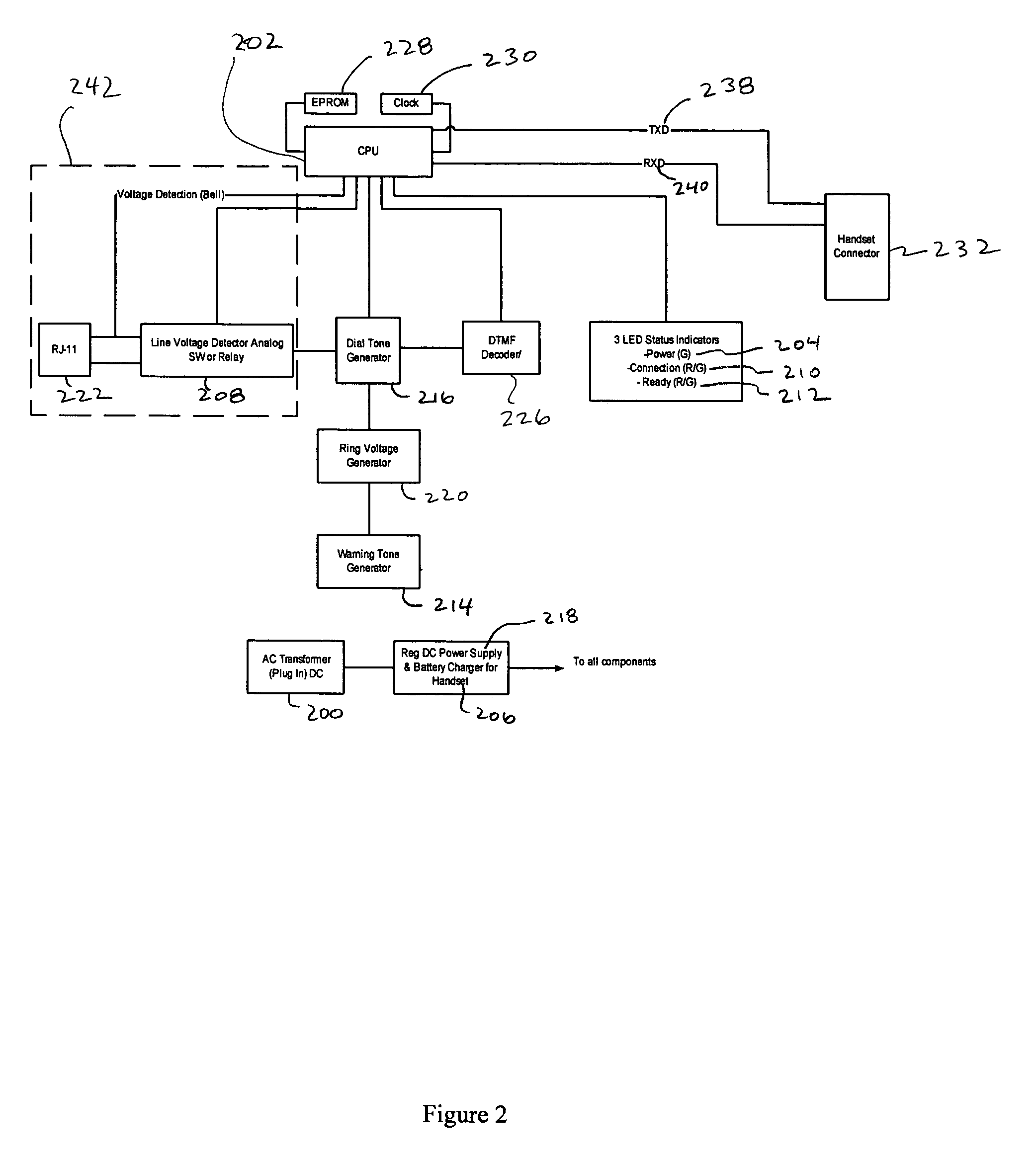
[0069]A central processing unit (“CPU”) 202 operates based on instructions received from an Electrically Programmable Read Only Memory (“EPROM”) 228, which is connected to the CPU 202. The EPROM 228 instructions provide for the operational features described herein, and are encrypted to prevent reverse engineering of the encoded software. A clock 230 is also connected to the CPU 202. The CPU 202 is connected to a handset connector 232 which interfaces with the handheld wireless telephone 100a. In the first embodiment, connector 232 is an edge type connector 232. Data is transmitted and received between the CPU 202 and the handset connector 232 via transmit data 238 and receive data 240 connections.

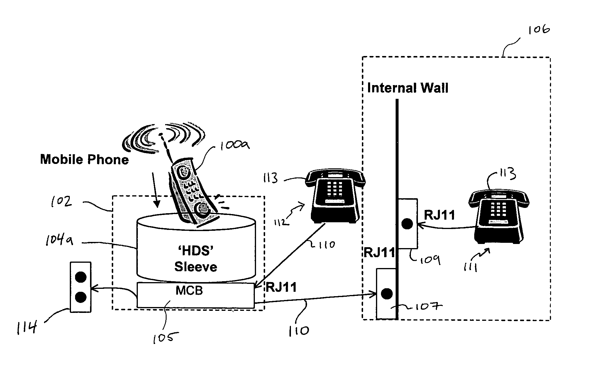
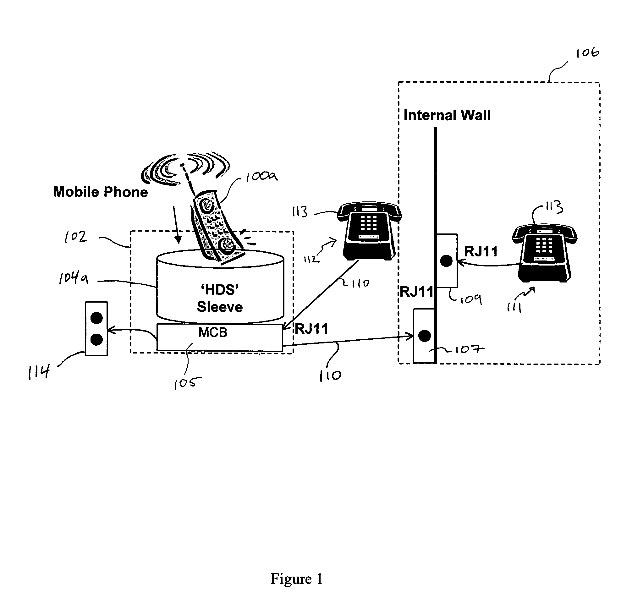
[0070]The docking station 102 connects to a wireline telephone system 106 and / or a standalone wireline telephone 112 via a standard female RJ-11 connector 222. Other connectors 222 may be used as will be evident to those skilled in the art. The docking station 102 may also be configured wi...

second embodiment

[0144]The flow diagrams of FIGS. 11, 12, 13 and 14, also illustrate functionality of the

[0145]Referring to FIG. 11, the initial start-up routine of the docking station 102′ is illustrated. In step S-1, electricity flows from the power source 114 to the connecting sleeve 104a′. In step S-2, the controls 706a′, 750′ signal the power status indicator LEDs 204′, 714a′ to illuminate green if power is supplied to the main controller box 105′ and connecting sleeve 104a′, respectively. If no power is available, the power status indicator LEDs 204′, 714a′ remain off. One or both of the RJ-11 telephone jacks 401′, 402′ are used in step S-3 to connect the docking station 102′ to a conventional telephone system 106 and / or a standalone conventional telephone 112.

[0146]In conjunction with the voltage detector 208′, the control 750′ evaluates whether voltage is present in the wireline (step S-4). If voltage is present, then the control 750′ instructs the connection status indicator LED 210′ to dis...


PUM


Abstract

The present invention features a docking station for connecting a conventional wireline telephone or system of conventional telephones to one or more handheld wireless telephones, enabling a conventional wireline telephone to send calls to and receive calls from a wireless telephone network. This arrangement can eliminate the requirement for a separate wireline telephone service. The wireless telephone may be easily removed from the docking station for independent use as a mobile wireless telephone. The docking station is provided with a specially configured removable connecting sleeve which may be used to connect a particular make and model of handheld wireless telephone to the docking station. The docking station may comprise more than one connecting sleeve so that more than one handheld wireless telephone may be accessed by a wireline telephone connected to the docking station. Docking station circuitry simulates the familiar conventional wireline telephone environment so that a conventional wireline telephone may access the wireless network in the same manner that landline telephone network is accessed.

Description

FIELD OF THE INVENTION[0001]The field of the invention relates generally to electronic telecommunications devices, systems and methods for interfacing between wireline and wireless telephones.BACKGROUND OF THE INVENTION[0002]Conventional (“wireline”) telephone systems require a physical connection (a “landline”) to be established between the telephone unit and the local telephone company central office. These systems are particularly expensive in rural areas where costly transmission lines must be constructed. Wireline telephones include those that are connected by copper wire, fibre optics, and cable and are not limited to simply metallic connections.[0003]Since conventional wireline telephone systems are fixed in place, those who require the use of a mobile telephone often must incur additional expense by subscribing to a cellular telephone service and by purchasing new telephone equipment to connect to a wireless telephone network, such as a cellular telephone network. In additio...

Claims


Application Information

Patent Timeline
Patent Type & Authority Patents(United States)
IPC IPC(8): H04M1/725
CPCH04M1/725
Inventor OSPALAK, STEPHEN SEANBLUMENTHAL, ROBERT E.KAICHIS, GEORGEHAW, DAVID CHARLESOKUMURA, HIROAKI
Owner TELUS CORP
Why Eureka
Try Eureka