
Device for automated manipulation of articles

a technology for manipulating devices and articles, applied in manipulators, conveyors, conveyor parts, etc., can solve problems such as negative affecting the aesthetic appearance of articles, and achieve the effect of greatly reducing the space required for inserting gripping devices on belts

Inactive Publication Date: 2005-12-27
IMT ROBOT
View PDF8 Cites 10 Cited by
  • Summary
  • Abstract
  • Description
  • Claims
  • Application Information

AI Technical Summary

Benefits of technology

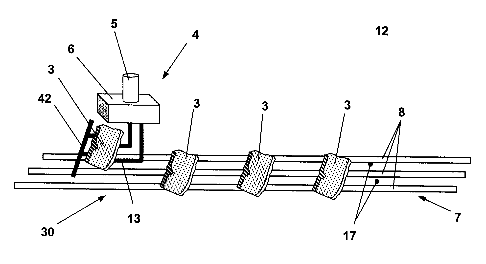
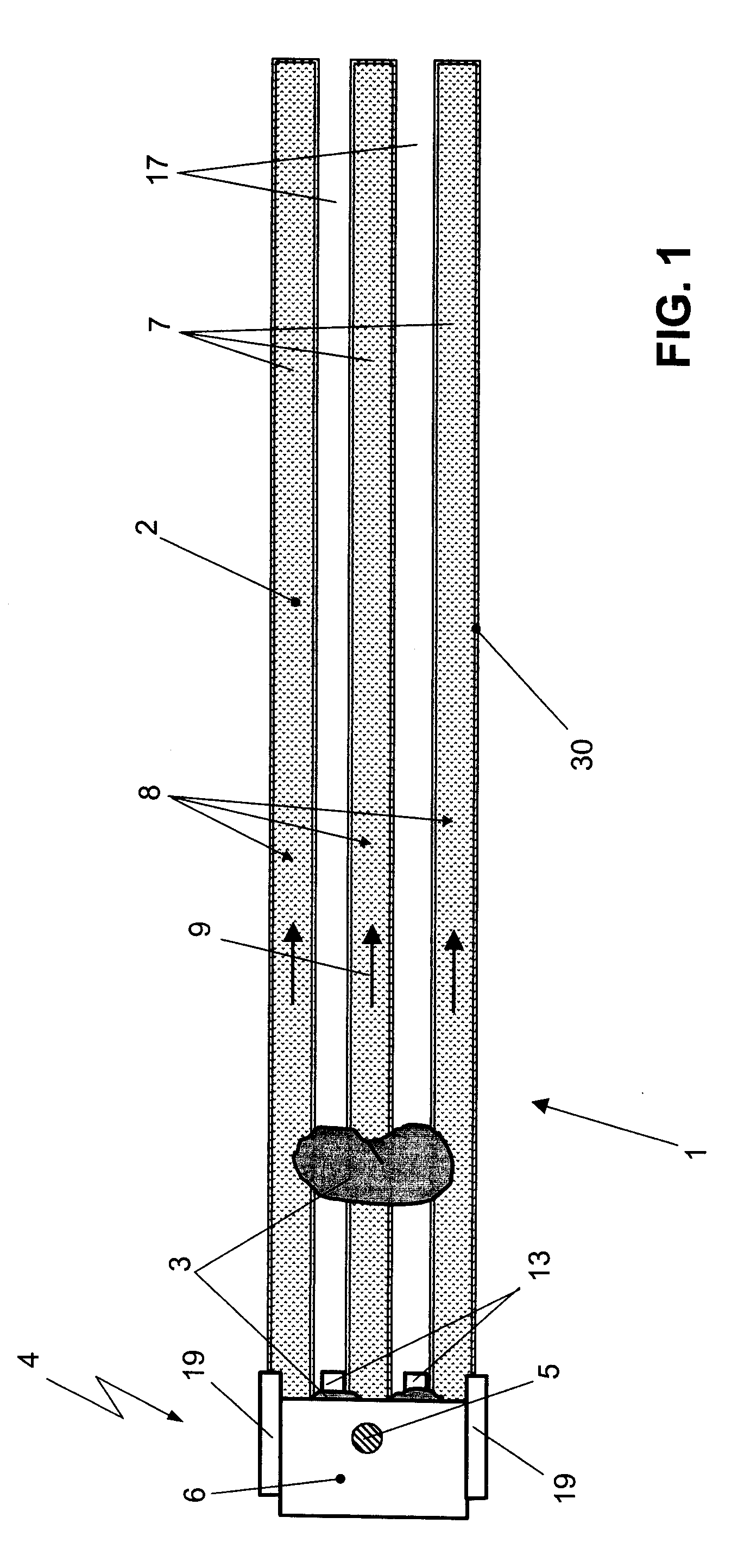
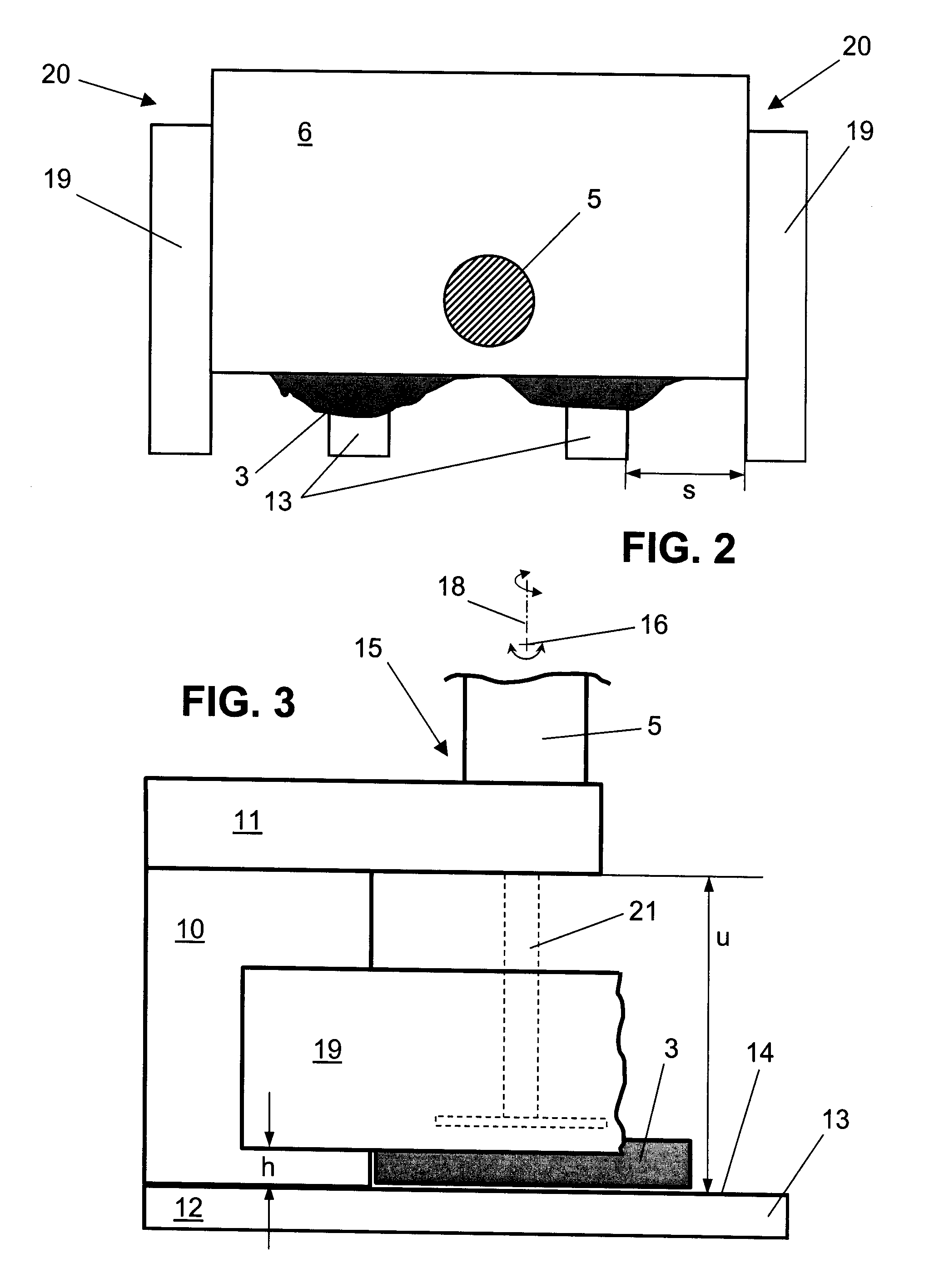
[0008]By configuring the working surface so as to be comprised of longitudinal elements with interposed longitudinal gaps, the articles are resting on a grid or the like so that the gripping device with a gripping finger can move into the longitudinal gap and move into a position underneath the article. By lifting the gripping device, the article is lifted off the working surface and, along the further movement path to the target location, is safely secured within the gripping device exclusively by the generated acceleration forces in combination with the force of gravity. For placing the articles, the acceleration forces are also used in that the article is released from the gripping fingers by accelerating the gripping device and is deposited by retracting the gripping device. The actions of holding and placing of the article can be enhanced by positioning the center of gravity of the article between an axis of rotation and a rear wall of the gripping device. In this way, the gripping device can be comprised of primarily immobile components that are arranged rigidly on the gripping device so that the gripping device itself has neither joints, adjusting elements nor gaps for allowing movement between parts into which the meat juice or similar liquids could penetrate. The gripping device, comprised exclusively of immobile components, fulfills also highest hygiene requirements and can be cleaned simply and quickly. For example, by means of a simple shower the gripping device can be kept clean even during extended operating periods.
[0010]Expediently, the lateral surfaces of the gripping device are at least partially closed by lateral support flanges in order to ensure even for great lateral accelerations a safe securing action of the article in the gripping device. In this way, even quick rotational movements about the vertical axis of the manipulator arm can be carried out.
[0012]In a further embodiment of the invention, the longitudinal elements and the longitudinal gaps between the longitudinal elements are aligned transversely to the transport direction of the conveyor belt wherein the gripping device for receiving the article moves transversely to the transport direction of the conveyor belt into a position underneath the article. This has the advantage that the free space required for inserting the gripping device on the belt is greatly reduced so that the articles can be placed closer together in this way. Lowering of the gripping device to the level of the belt can be initiated adjacent to the belt in order to then move the gripping device, when entering the longitudinal gaps that extend transversely to the transport direction of the belt, simultaneously in the transport direction of the conveyor belt for picking up the article.

Problems solved by technology

Moreover, such vacuum gripping devices leave contact traces on the articles that may negatively affect the aesthetic appearance of the article.

Method used


Image

  • Device for automated manipulation of articles
  • Device for automated manipulation of articles
  • Device for automated manipulation of articles

Examples


Embodiment Construction

[0021]The device illustrated in FIG. 1 serves for automated manipulation of articles, for example, pieces of meat (in the form of slices of meat or the like), fish (for example, in the form of filets), poultry (for example, as portioned parts), or similar food articles. The illustrated working area 1 has a working surface 2 for the articles 3 that in the illustrated embodiment are slices of meat (cutlets or the like). In the working area 1, a manipulator 4 is arranged; the end of the manipulator arm 5 as well as the gripping device 6 fastened to the manipulator arm 5 are the only parts of the manipulator 4 that are illustrated. The manipulator can be a robot or a similar device that can pivot and rotate the gripping device and can guide the gripping device along particularly amovement path. The robot movements are expediently predetermined such that acceleration forces act on the picked-up article 3 that can be even a multiple of the acceleration due to gravity.

[0022]In the illustra...


PUM

PropertyMeasurementUnit
Timeaaaaaaaaaa
Accelerationaaaaaaaaaa
Areaaaaaaaaaaa

Abstract

A device for automated manipulation of articles along a predetermined movement path has a working area having a working surface for articles. The device also has a manipulator with a gripping device for moving the articles. The working surface consists of neighboring longitudinal elements, wherein longitudinal gaps are formed between the neighboring longitudinal elements. The griping device has at least one gripping finger that can be lowered into the longitudinal gaps between the neighboring longitudinal elements and moved into a position underneath an article for picking up the article. The article is essentially secured in the gripping device by a combination of acceleration forces generated along a movement path of the gripping device and of the force of gravity.

Description

BACKGROUND OF INVENTION[0001]1. Field of the Invention[0002]The invention relates to a device for automated manipulation of articles such as meat, fish, poultry or the like along a predetermined movement path. The device is comprised of a working surface for the articles provided in a working area as well as a manipulator arranged within the working area and comprising a gripping device for the articles to be moved, wherein the working surface is comprised of longitudinal elements with longitudinal gaps formed between neighboring longitudinal elements. The gripping device has gripping fingers that can be lowered into the longitudinal gaps between neighboring longitudinal elements of the working surface and can be moved into a position underneath the article for picking up the article.[0003]2. Description of the Related Art[0004]With such devices, articles such as meat, fish, poultry or the like are moved by manipulators such as robots from a first position, for example, on a belt, i...

Claims


Application Information

Patent Timeline
IPC IPC(8): B25J9/00B25J15/00B65G47/52B65G47/66
CPCB25J9/0093B25J15/00B25J11/0045B65G47/52B65G2207/26B65G2207/38
Inventor NAGLER, PETER
Owner IMT ROBOT
Learn More