Control system and method for a continuously variable transmission

a transmission system and control system technology, applied in the direction of gearing elements, clutches, gearing components, etc., can solve the problems of small but imperceptible engine speed change, difficult process of clutch engagement, and reducing overall time taken, so as to reduce the overall time taken. , the effect of sacrificing the quality of shift or control robustness

Inactive Publication Date: 2005-12-27
ALLISON TRANSMISSION INC
View PDF8 Cites 40 Cited by
  • Summary
  • Abstract
  • Description
  • Claims
  • Application Information

AI Technical Summary

Benefits of technology

[0016]It is an object of the present invention to reduce the overall time taken to

Problems solved by technology

Since switching the control operation of the variator inevitably introduces a period of diminished capability alternative drive means must be provided during the process.
(a) Fill and “lock” the next regime clutch. The clutch is applied by a piston and cylinder that takes a finite time to fill. Sufficient pressure must be applied to the piston to prevent slip but if applied before or after synchronous ratio is reached, will produce “shift shock”.
(b) Reverse the control force applied to the variator. This will reverse the power transmitted by the variator. However the two locked regime clutches will ensure power transmission. Fixed ratio operation for a

Method used


Image

  • Control system and method for a continuously variable transmission
  • Control system and method for a continuously variable transmission
  • Control system and method for a continuously variable transmission

Examples


Embodiment Construction

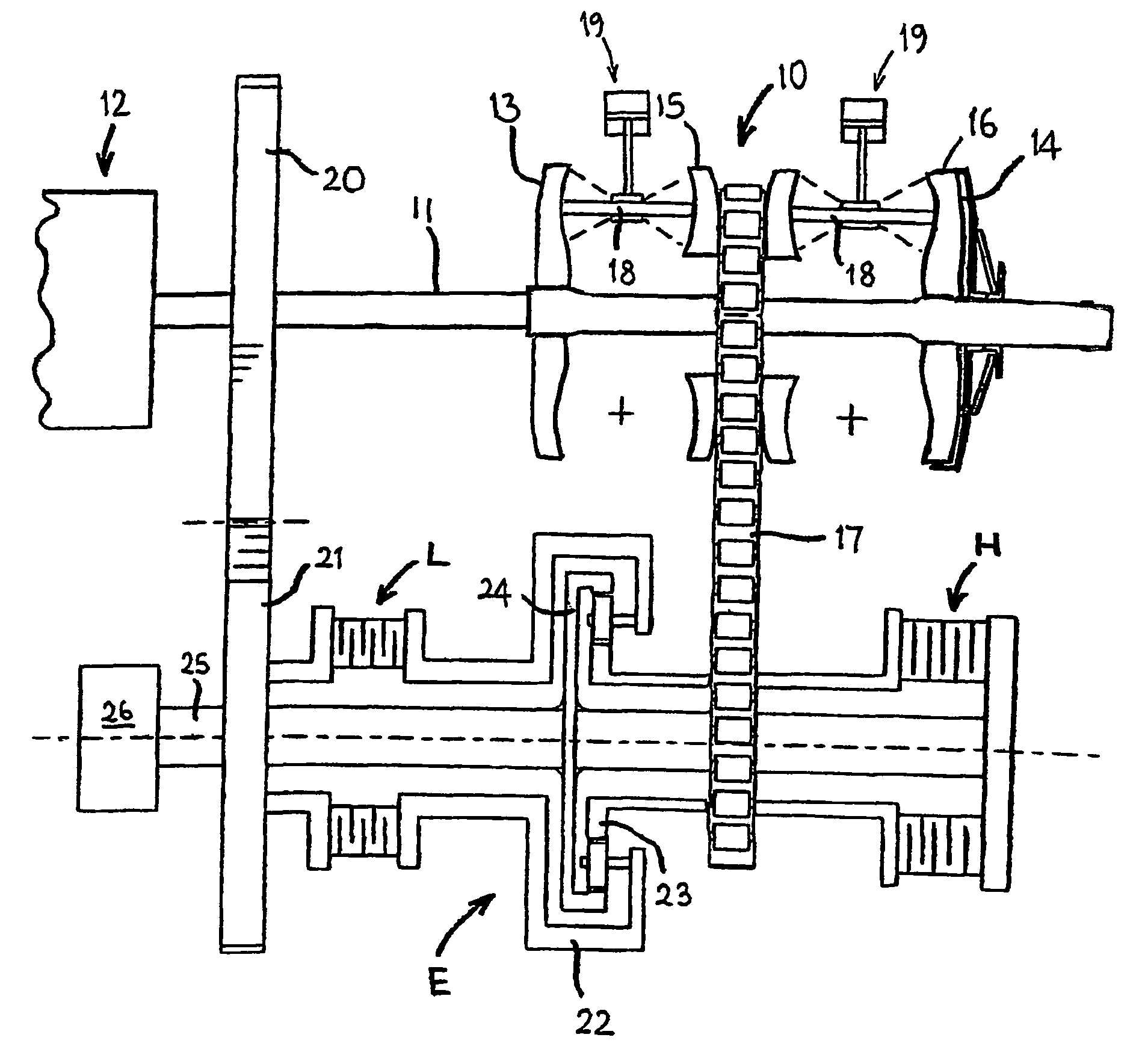
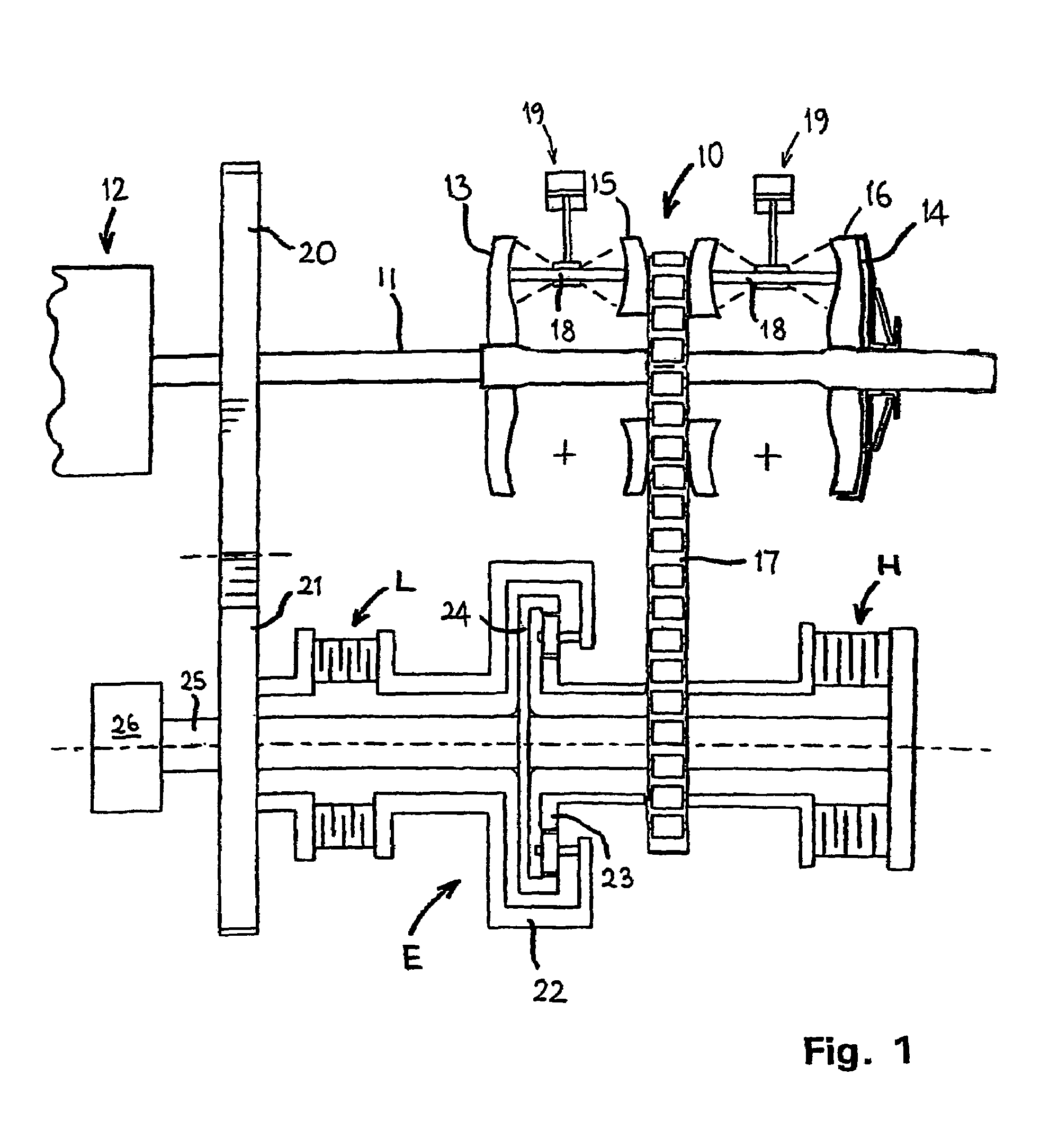
[0037]FIG. 1 illustrates one embodiment of continuously variable transmission controlled in accordance with the present invention. The transmission shown is for a front wheel drive vehicle but the invention is equally applicable to rear wheel drive and all wheel drive transmissions.

[0038]The transmission as illustrated is generally conventional. A toroidal race-rolling traction type continuously variable ratio transmission unit 10 (hereinafter referred to as variator 10) has an input shaft 11 from an engine 12. The input shaft 11 drives a toroidally-recessed disc 13, 14 at each end of the variator 1. A pair of similar discs 15; 16 facing respective ones of the driven discs 13, 14, is connected to a variator output sprocket (not visible in the drawings) around which a chain 17 is entrained. As described more fully in GB-A-2108600 and GB-A-2100372, sets of rollers 18 are mounted between opposing faces of these discs to transmit drive from the input shaft 11 to the chain 17 with a gear...


PUM


Abstract

A control system for a multi-regime continuously variable ratio transmission system. The system has input and output shafts and a continuously variable ratio transmission unit (“variator”) connected to the input shaft. Also included is a mixing epicyclic gear train with a first input gear coupled to the input shaft, a second input gear connected to the variator output and an output gear driving an output shaft. Fluid-pressure actuated clutches engage the outputs and ratio combinations to operate the CVT in a number of regimes. The control system includes means for engaging the clutch of a new regime, retaining both clutches engaged in a synchronous mode and disengaging the clutch of the old regime. The control system also has means for applying fluid pressure to engage the new regime clutch in a single stage at the maximum available clutch engaging fluid pressure.

Description

TECHNICAL FIELD[0001]The present invention relates to a control system and method for continuously variable transmission systems suitable for use in motor vehicles, for example. In particular, it is concerned with controlling multi-regime transmission, for example a two-regime transmission low and high), an example of which is known from DE-A-2814222.BACKGROUND ART[0002]A further continuously variable ratio transmission of the toroidal race rolling traction type is described in GB-A-2108600. A two regime continuously variable ratio transmission system, using a toroidal race rolling traction transmission unit and having another connection between the variator and the two epicyclic gear trains, is known from GB-A-2100372.[0003]In such multi-regime transmissions, each regime is selected by a clutch which is engaged by the application of hydraulic fluid pressure as required by the transmission control software. Each regime covers part of the overall ratio spread of the transmission and ...

Claims


Application Information

Patent Timeline
IPC IPC(8): F16H37/08F16H61/00F16H61/06F16H61/664
CPCF16H61/0021F16H61/061F16H37/086F16H61/6648F16H2037/0886
Inventor MURRAY, STEPHEN WILLIAM
Owner ALLISON TRANSMISSION INC
Why Eureka
Try Eureka