Frequency measuring circuit and resonant pressure sensor type differential pressure/pressure transmitter using the frequency measuring unit

Active Publication Date: 2005-12-27
YOKOGAWA ELECTRIC CORP
View PDF12 Cites 11 Cited by
  • Summary
  • Abstract
  • Description
  • Claims
  • Application Information

AI Technical Summary

Benefits of technology

[0011]To achieve the above-mentioned object, according to a first aspect of the present invention, there is provided a frequency measuring circuit which comprises: a first counter which counts reference clocks during one cycle of a signal to be measured or a period which is integer times as long as the one cycle, a time difference detection circuit which detects time difference between the signal to be measured and the reference clock, a time expansion circuit which expands an output pulse width of the time difference detection circuit by a given magnification, and a second counter which counts the reference clocks during the pulse width which is expanded by the time difference expansion circuit, wherein the frequency of the signal to be measured is obtained based on count values of the first and second counters. Due to such a constitution, the fast processing and the high resolution of measurement can be achieved without increasing the frequency of the reference clock.
[0012]According to a second aspect of the present invention, in the frequency measuring circuit according to the first aspect of the present invention, the count value of the second counter is divided by the given magnification with which the time expansion circuit expands the pulse width, and a result of the division is added to the count value of the first counter so as to obtain the frequency of the signal to be measured. Due to such a constitution, the frequency can be easily obtained.
[0013]According to a third aspect of the present invention, in the frequency measuring circuit according to the first or second aspect of the present invention, the time difference detection circuit outputs a pulse signal having the pulse width from a point of time that a level of the signal to be measured is changed to a point of time that a level of the reference clock is changed. Due to such a constitution, the time difference signal can be easily obtained.

Problems solved by technology

However, the resonant pressure sensor-type differential pressure / pressure transmitter having such a constitution has a following drawback.
However, when the gate time is shortened, there has been a drawback that the resolution of the count value is lowered.
Although it is necessary to elevate the frequency of the reference clock to increase the resolution, this elevation of the frequency brings about the increase of power consumption.
Since the two-wire differential pressure / pressure transmitter is required to exhibit the small power consumption, there has been also a drawback that the increase of the frequency of the reference clock is difficult.

Method used


Image

  • Frequency measuring circuit and resonant pressure sensor type differential pressure/pressure transmitter using the frequency measuring unit
  • Frequency measuring circuit and resonant pressure sensor type differential pressure/pressure transmitter using the frequency measuring unit
  • Frequency measuring circuit and resonant pressure sensor type differential pressure/pressure transmitter using the frequency measuring unit

Examples


Embodiment Construction

[0028]Preferred embodiments of the present invention are explained in detail hereinafter in conjunction with attached drawings.

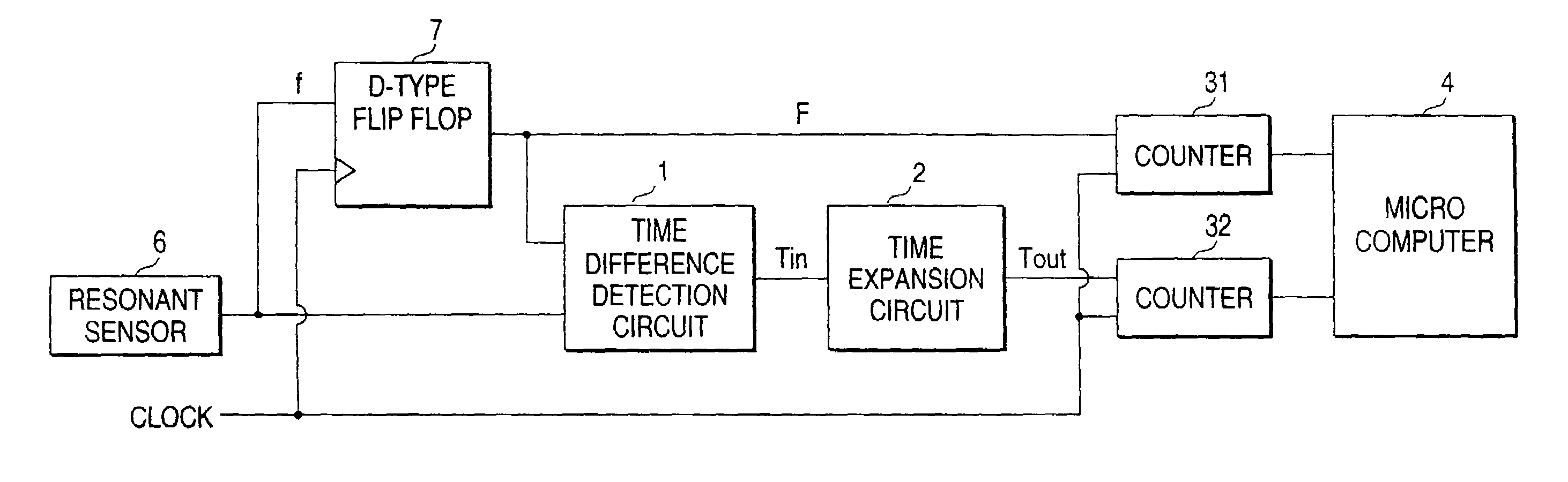
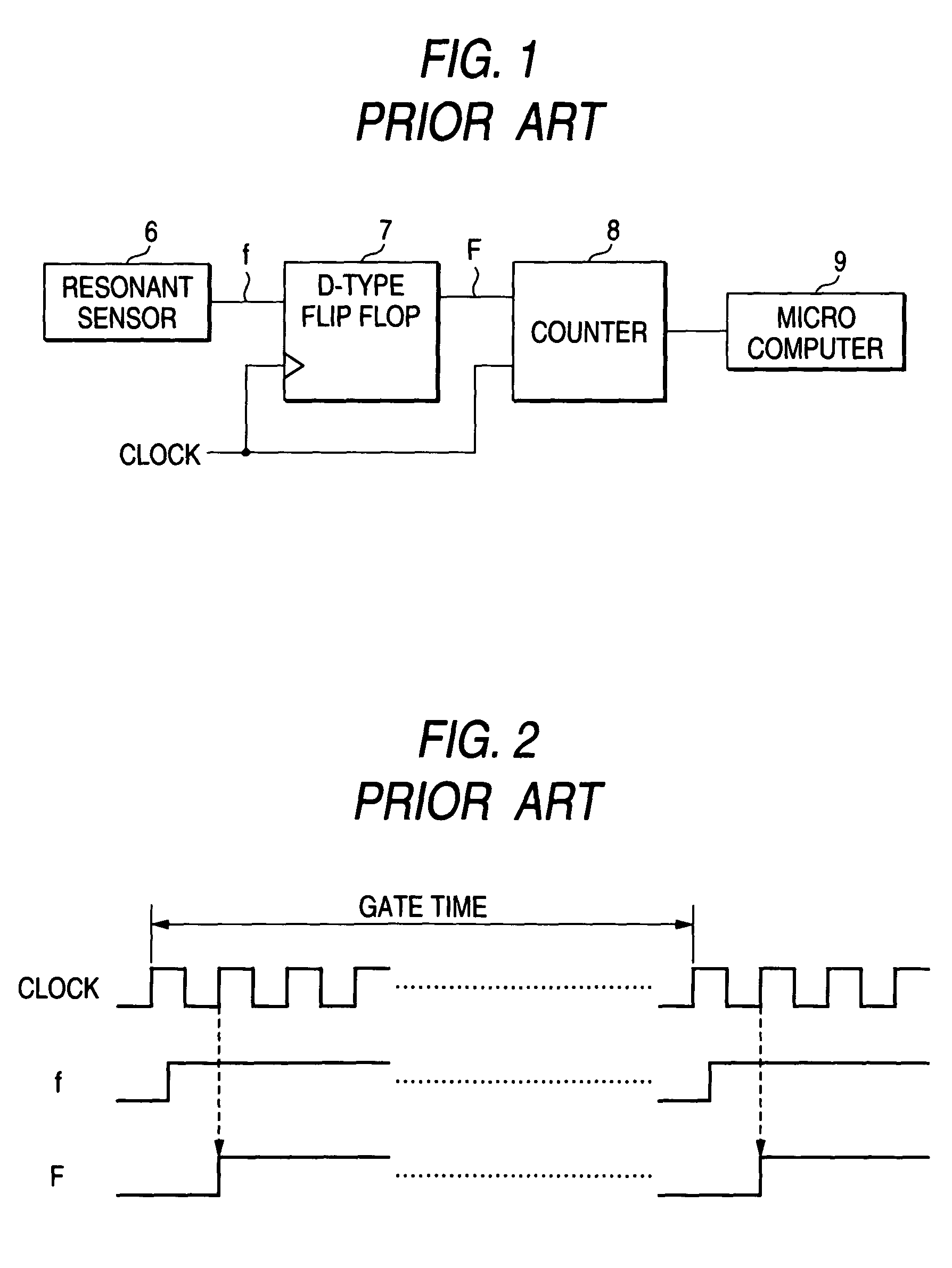
[0029]FIG. 3 is a constitutional view showing one embodiment of a frequency measuring circuit used in a differential pressure / pressure transmitter according to the present invention. Here, components which are identical with the components shown in FIG. 1 are indicated by same numerals and their explanation is omitted.

[0030]In FIG. 3, numeral 1 indicates a time difference detection circuit to which an output f of a resonant pressure sensor 6 and an output F of a D-type flip flop 7 are inputted. The time difference detection circuit 1 outputs a signal Tin which assumes a low level at a rise of the output f and assumes a high level at a rise of the output F which follows the output f. That is, the output Tin of the time difference detection circuit 1 is a signal which has a pulse width of time difference between the outputs f and F.

[0031]Numeral 2 indicates a ...


PUM


Abstract

A time difference signal having a pulse width corresponding to the time difference between an output of a resonant pressure sensor and a reference clock is prepared. The pulse width of the time difference signal is expanded by a given magnification. Based on a count value obtained by counting the reference clock during the expanded pulse width and a count value obtained by counting the reference clock during one cycle of the output of the resonant pressure sensor or a period which is integer times as long as the one cycle, the output frequency of the resonant pressure sensor is obtained. It is possible to obtain the fast processing and the high resolution without increasing the frequency of the reference clock.

Description

BACKGROUND OF THE INVENTION[0001]1. Field of the Invention[0002]The present invention relates to a frequency measuring circuit which can measure the frequency of a signal to be measured at a high speed and with high resolution without speeding up a reference clock and a resonant pressure sensor type differential pressure / pressure transmitter using the frequency measuring circuit.[0003]2. Description of the Related Art[0004]FIG. 1 shows the constitution of a frequency measuring circuit used in a two-wire resonant pressure sensor type differential pressure / pressure transmitter. A resonant pressure sensor 6 outputs a signal f having frequency corresponding to a measured pressure. The signal f is inputted to a D-type flip flop 7 and is converted into a signal F which is in synchronism with a rise of a reference clock. The signal F and the reference clock are inputted to a counter 8. The counter 8 counts the reference clocks during one cycle of the signal F or a period integer times as l...

Claims


Application Information

Patent Timeline
IPC IPC(8): G01L9/00G01R23/10G04F10/04G04F10/10H03K5/06
CPCG01L9/0008G01R23/10G04F10/04G04F10/105H03K5/06
Inventor HORIO, YASUAKINIKKUNI, MASAAKIMORIYA, MASAHIKOYOSHINO, HIROKI
Owner YOKOGAWA ELECTRIC CORP
Why Eureka
Try Eureka