
Image sensing apparatus which carries out optimum exposure control of subject

a technology of image sensing and subject, which is applied in the direction of exposure control, color signal processing circuit, instruments, etc., can solve the problems of not always providing a state of exposure control, the image resulting from photography is too bright or too dark, and the photographer is difficult to optimally adjust the exposure of the subject, etc., to achieve the effect of reducing the size of the apparatus

Inactive Publication Date: 2005-12-27
CANON KK
View PDF10 Cites 8 Cited by
  • Summary
  • Abstract
  • Description
  • Claims
  • Application Information

AI Technical Summary

Benefits of technology

[0035]As a result, an optimum image conforming to various subjects and photographic conditions is obtained while maintaining optimum balance between the state of exposure, intended by the photographer, of the zone of the subject, and the state of exposure at the periphery of the subject.
[0038]In a case where a zone of the subject intended by the photographer is not contained in a newly captured video signal upon elapse of a prescribed period of time or as the result of zooming, holding of exposure is suspended, thereby making it possible to deal rapidly with a change in photographic conditions.
[0040]This makes it possible to prevent a deterioration in the balance of overall exposure of the scene caused by improper exposure at the periphery of the subject and the occurrence of saturation or darkness even though the intended zone of the subject is properly exposed.
[0043]As a result, an optimum image conforming to various subjects and photographic conditions is obtained while maintaining optimum balance between the state of exposure, intended by the photographer, of the zone of the subject, and the state of exposure at the periphery of the subject.
[0046]Further, the screen is a monitor screen of an electronic viewfinder. If the photographer merely designates an intended zone of a subject, the exposure is adjusted to the optimum state automatically. As a result, the photographer is freed from having to gaze steadily at the monitor screen. This makes it possible to use an electronic viewfinder having a sufficiently small monitor screen, thus contributing to a reduction in the size of the apparatus.

Problems solved by technology

For example, it is difficult for the photographer to optimally adjust the exposure of the subject at all times while maintaining the balance between the exposure of the subject and the exposure of the surroundings of the subject.
Often the image resulting from photography is too bright or too dark (what is caled saturation or noise (darkness)).
However, even the photometric methods described above do not always provide a state of exposure control that is intended by the photographer.
This results noise (darkness).
As a consequence, the size of the screen is small.
Furthermore, in an EVF using liquid-crystal display means for the purpose of providing a color display, the dynamic range is insufficient.
Thus, the small size of the screen and the characteristics of the liquid-crystal display means make it difficult to accurately discern the state of exposure of the subject.
As a result, it is difficult to set the optimum exposure and a disparity can develop between the state of exposure intended by the photographer and the state of exposure actually set.
Further, even if subject exposure intended by the photographer is achieved, the periphery of the subject results saturation or darkness, and the resulting video may have poor balance in terms of the exposure of the scene overall.
Furthermore, since complicated key operation is necessary, the photographer is required to have some degree of photographic experience.
A photographer with little photographic experience cannot master operation with ease.

Method used


Image

  • Image sensing apparatus which carries out optimum exposure control of subject
  • Image sensing apparatus which carries out optimum exposure control of subject
  • Image sensing apparatus which carries out optimum exposure control of subject

Examples


first embodiment

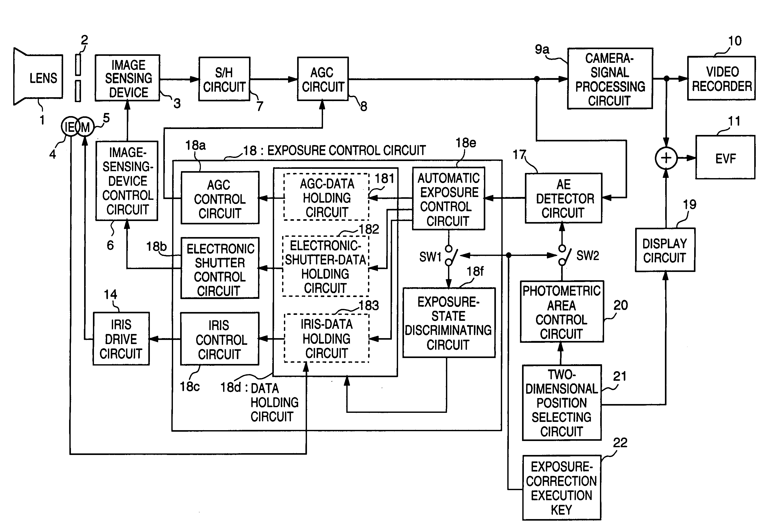
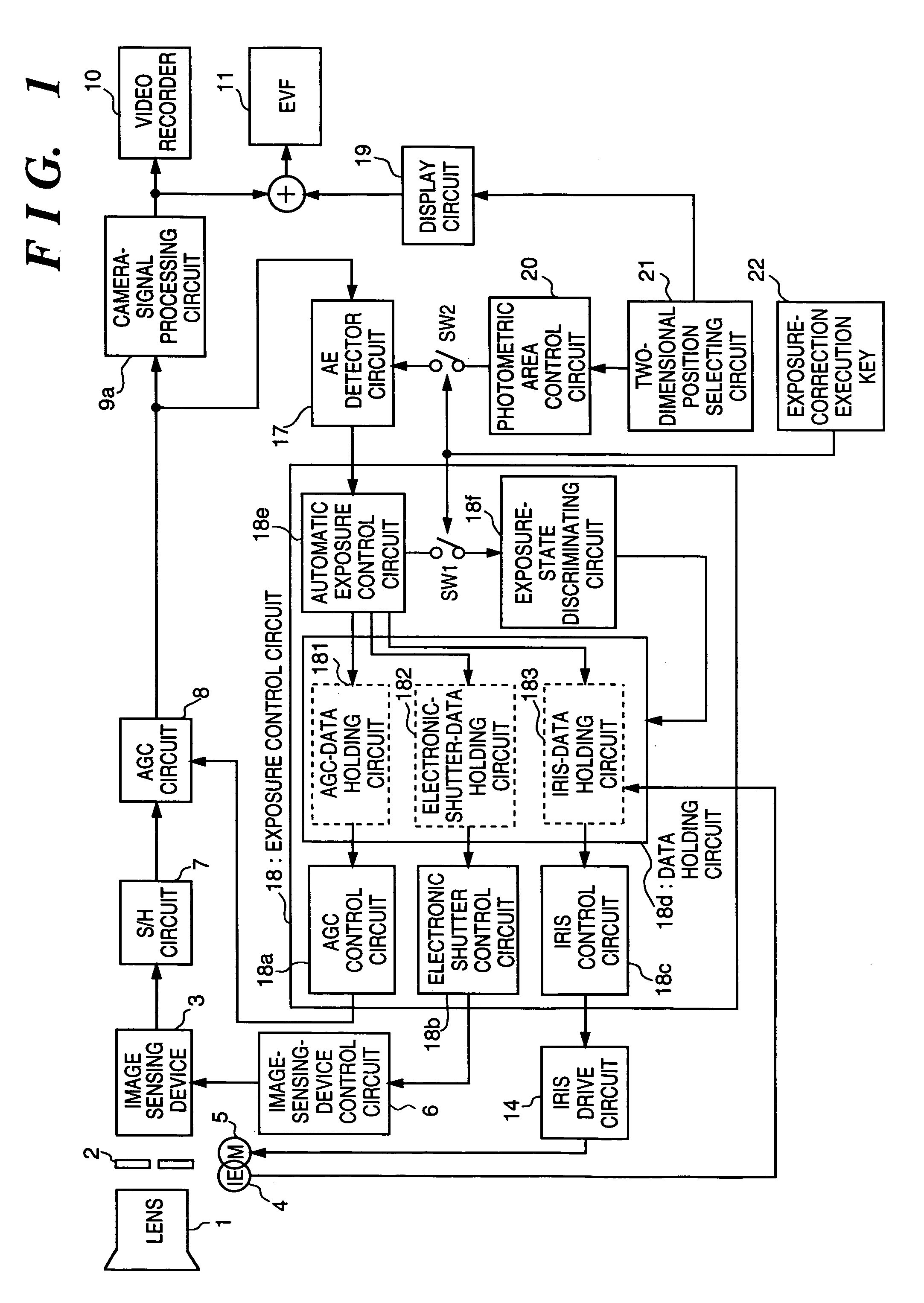
[0063]FIG. 1 is a block diagram illustrating the construction of an image sensing apparatus according to a first embodiment of the present invention. Components identified by reference characters identical with those of the prior-art example shown in FIG. 4 have similar functions and need not be described in detail again.

[0064]The apparatus of FIG. 1 differs from that of FIG. 4 in the provision of two-dimensional position selecting means 21, photometric area control means 20 and an exposure-correction execution key 22, and in that the functions of an AE detector circuit 17 and exposure control circuit 18 are different. In other aspects the process through which the video signal is processed is similar to that of the prior art (FIG. 4).

[0065]Ordinarily, control is similar to that of the prior art shown in FIG. 4. Specifically, a change in exposure due to a change in the subject is detected from the video signal by means of the AE detector circuit 17, and, on the basis of the output s...

third modification

of First Embodiment

[0103]FIG. 3 is a block diagram illustrating the construction of an image sensing apparatus according to a third modification of the first embodiment of the present invention. This differs from the first embodiment of FIG. 1 in the construction of an exposure control circuit 24.

[0104]The exposure control circuit 24 has circuit components 24a˜24c corresponding to the circuits 18a˜18c, respectively, of FIG. 1. The circuits 18d, 18e and 18f of FIG. 1 correspond to the circuits 24f, 24g and 24h, respectively, of FIG. 3.

[0105]The exposure control circuit 24 in this modification differs from the exposure control circuit 18 in the first embodiment. A LUT data converting circuit 24d and a LUT 24e, in which data indicative of exposure control parameters have been stored in the manner shown at ② in FIG. 6, are provided between a data holding circuit 24f and an iris control circuit 24c, AGC control circuit 24a and electronic shutter control circuit 24b.

[0106]Further, an exp...

second embodiment

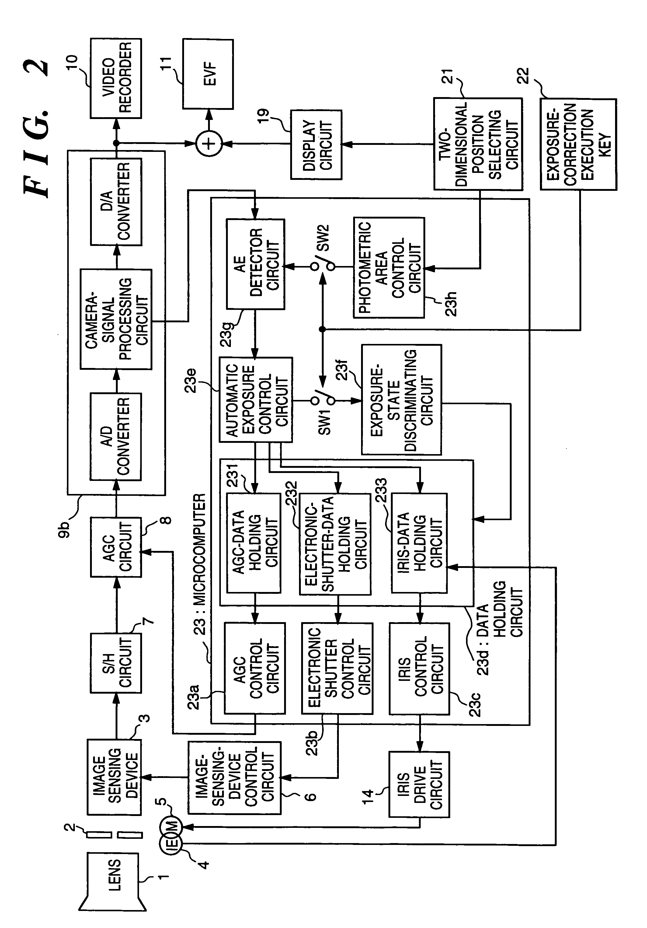
[0108]A second embodiment of the invention will now be described with reference to FIG. 8, which is a block diagram of an image sensing apparatus according to the present invention. Elements corresponding to those in FIG. 1 of the first embodiment and FIG. 4 of the prior art are designated by like reference characters. The functions of the elements identified by like reference characters are the same as in first embodiment and need not be described again. In this embodiment, the arrangement of the image sensing apparatus of the first embodiment is further provided with an image information memory circuit 123 serving as means for storing image information, and an image information detecting circuit 124 serving as means for determining whether image information exists.

[0109]The operation of the second embodiment will now be described. Using the two-dimensional position selecting circuit 21, the photographer sets the fixed frame at the position of the subject for which the optimum stat...


PUM


Abstract

The state of exposure of a video zone corresponding to position information from a two-dimensional position selecting circuit that allows a photographer to select a desired video zone is detected, an exposure correction is performed by an exposure control circuit based upon a signal indicative of the detected state, and the state of exposure which prevails when optimum exposure has been attained is maintained. As a result, the state of exposure of a subject is corrected to an optimum exposure and the optimum exposure of the subject is maintained even if the state of exposure of the surroundings change owing to a change in zoom magnification or movement of the subject.

Description

BACKGROUND OF THE INVENTION[0001]1. Field of the Invention[0002]This invention relates to an image sensing apparatus so adapted that optimum exposure control is carried out with regard to any range of video signals obtained by imaging.[0003]2. Description of the Related Art[0004]The recent progress made in the field of video equipment such as video cameras has been remarkable and such equipment has been provided with greater functionality and capability. In order for such image sensing apparatus to be able to perform optimum photography at all times under a large variety of photographic conditions, exposure control is very important. For example, it is difficult for the photographer to optimally adjust the exposure of the subject at all times while maintaining the balance between the exposure of the subject and the exposure of the surroundings of the subject. Often the image resulting from photography is too bright or too dark (what is caled saturation or noise (darkness)).[0005]Exp...

Claims


Application Information

Patent Timeline
IPC IPC(8): H04N5/235
CPCH04N5/2351H04N23/71
Inventor TAMURA, KYOJITARIKI, MOTOI
Owner CANON KK
Learn More