Electrode arrangement as substitute bottom for an electrothermic slag smelting furnace

a technology of electrothermic slag and electrode arrangement, which is applied in the direction of electric heating of furnaces, lighting and heating apparatus, furnaces, etc., can solve the problems of reduced life of bottom linings, frequent repairs or replacements of bottom linings, and high wear of bottom linings, so as to facilitate the process of restarting the furnace

Inactive Publication Date: 2005-12-27
ARCONIC INC
View PDF13 Cites 10 Cited by
  • Summary
  • Abstract
  • Description
  • Claims
  • Application Information

AI Technical Summary

Benefits of technology

[0005]A principal object of the present invention is to provide an improved electrode arrangement for use in electrothermic slag smelting furnaces which eliminates a number of the problems in the prior art.
[0006]It has been discovered that one or more contacts located in the side wall of the furnace can act as a zero point for the current in the furnace, thereby substituting for the bottom lining of the furnace as an electrical contact. Using side wall contacts provides a number of advantages over using the bottom of the furnace as the contact surface.
[0009]Preferably, the side wall contacts are carbon bodies which are consumed in the furnace during operation and which are replaceable from outside the furnace. Preferably, there are openings in the side wall of the furnace to allow the side wall contacts to pass into the furnace. Each of the openings is equipped with a sealing means for maintaining a gas tight and liquid tight seal between the side wall and the side wall contact. It is preferred that the sealing means allows for radial movement of the contact into the furnace interior in order to compensate for the wear or consumption of the side wall contacts. It is also preferred that the furnace is equipped with a moving means for radially moving each of the side wall contacts into the furnace in order to compensate for the wear on the side wall contacts. Preferably, each of the side wall contacts is equipped with a moving means and each of the side wall contacts can be moved independent of the other side wall contacts to provide for individual adjustment of the side wall contacts in the furnace.
[0011]In another embodiment of the present invention, one or more of the side wall contacts is hollow and is equipped with a means for feeding charge or slag forming components through the hollow contact while preventing flow of slag through the hole in the contact.
[0013]Because of the electrode arrangement of the present invention, the furnace bottom lining does not need to be electrically conductive and the furnace lining can therefore be designed to withstand the liquid slag and the high temperatures which exist in the furnace. This means that the material that is used to make up the furnace bottom lining can be solely based on its ability to withstand high temperatures and liquid slag. Thus, the present invention makes possible to use the material for the bottom lining onto which a bottom layer of frozen slag has formed. The formation of frozen slag on the bottom lining can be accomplished by using a good thermally conductive material and subjecting the bottom to external cooling. Furthermore, the use of an electrically non-conductive bottom lining means that the bottom lining need not be electrically insulated from the rest of the furnace.
[0014]Preferably, the furnace of the present invention is equipped with a tap hole which is placed in the side wall of the furnace at a level below the side wall contacts. This allows for slag to be tapped from the furnace to below the level of the side wall contacts, thus, making it easier to restart the furnace.

Problems solved by technology

One of the disadvantages of the conductive bottom is that, because of the high wear on the bottom lining, the life of the bottom lining is reduced and repairs or replacements to the bottom lining are frequent.
The high wear on the bottom lining is due to the high temperature to which the bottom lining is subjected because the bottom lining is the zero point for the current that flows through the slag of the furnace.
Another major disadvantage to the conductive bottom lining is that when the furnace is shut down, restarting of the furnace is difficult due to the solidification or freeze-up of slag in the furnace during the shutdown.

Method used


Image

  • Electrode arrangement as substitute bottom for an electrothermic slag smelting furnace
  • Electrode arrangement as substitute bottom for an electrothermic slag smelting furnace
  • Electrode arrangement as substitute bottom for an electrothermic slag smelting furnace

Examples


Embodiment Construction

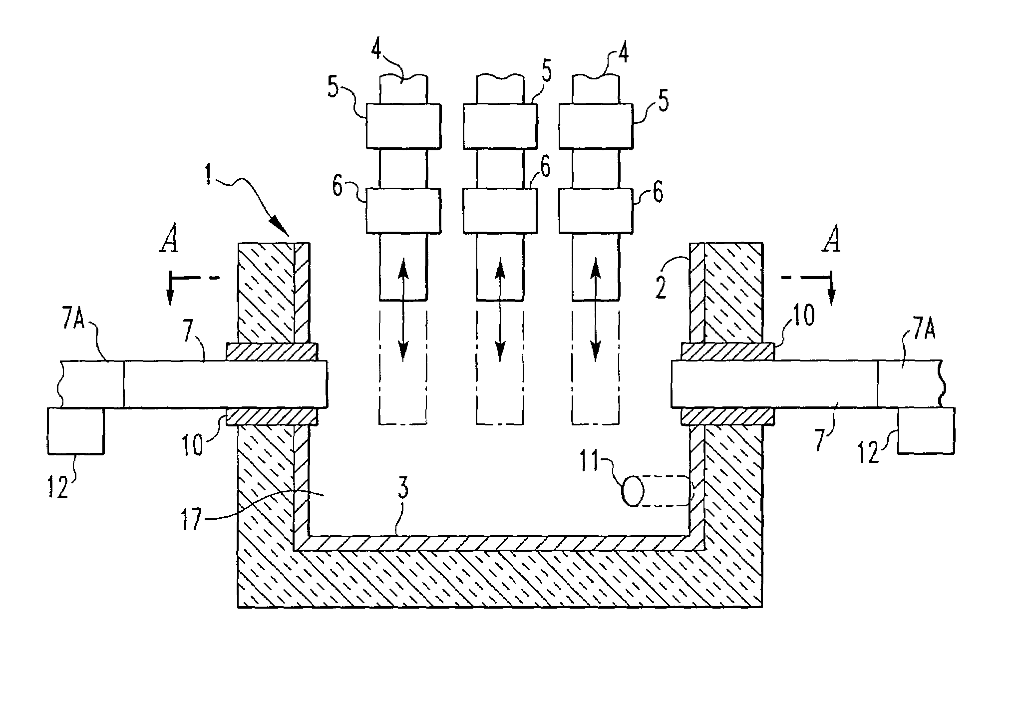
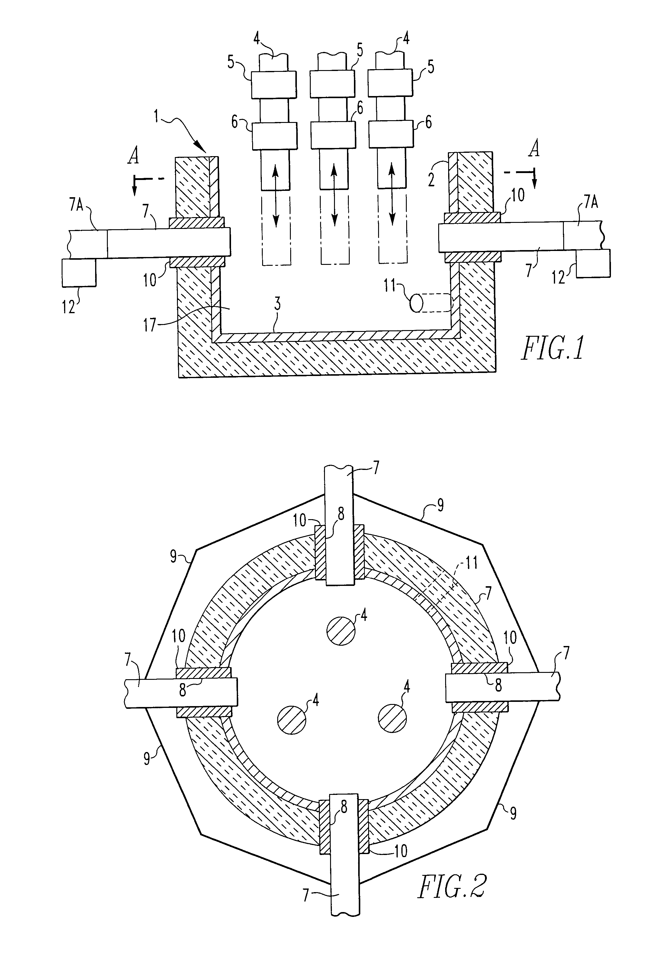
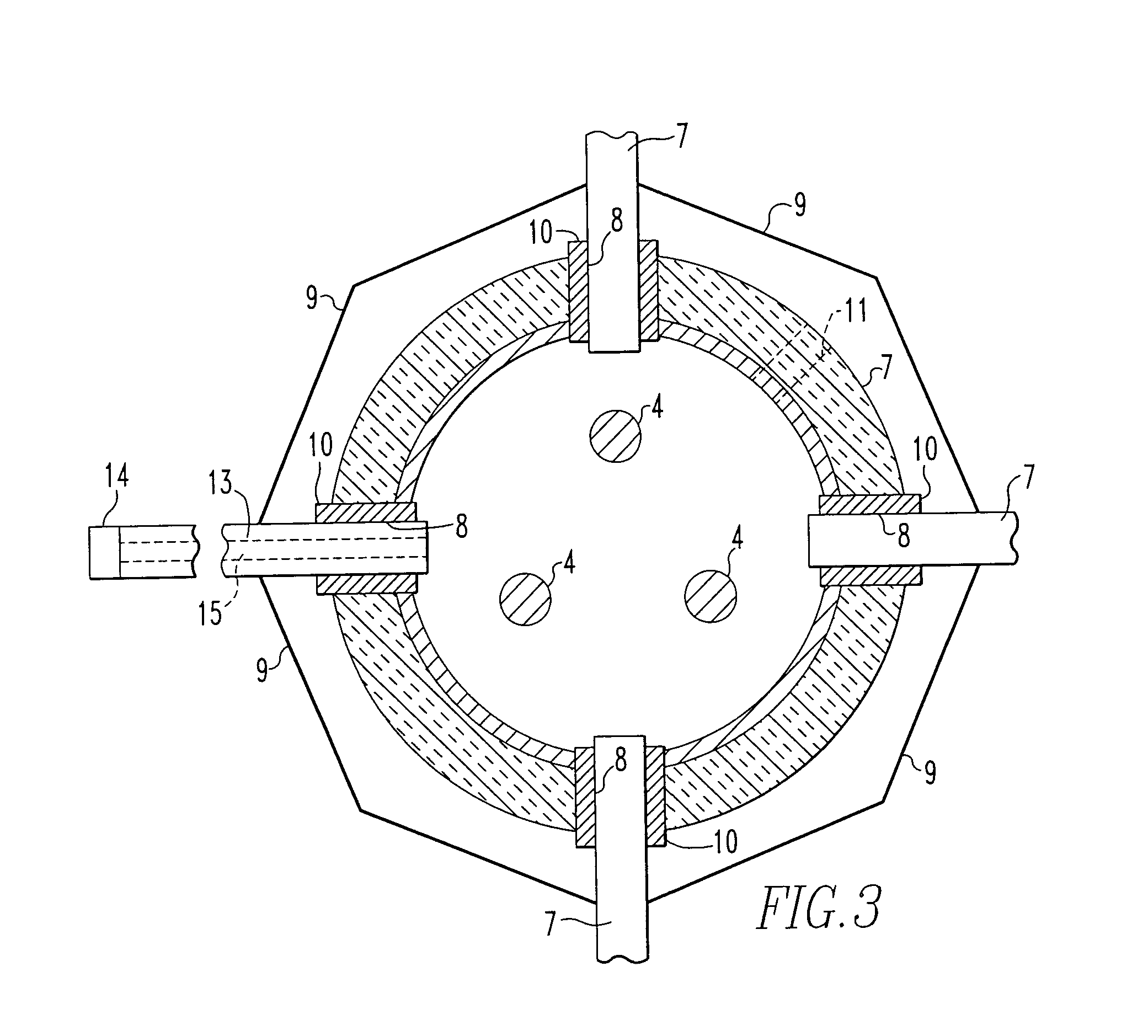
[0019]In FIG. 1, smelting furnace 1 has a furnace pot with side wall 2 and bottom or bottom lining 3. The bottom lining 3 preferably comprises an electrically insulating refractory material. Furnace 1 is equipped with three conventional vertical carbon electrodes 4. Electrodes 4 are equipped with holding and slipping means 5 to allow for vertical movement of the electrodes and current clamps 6 to provide electric current to electrodes 4 from a power source (not shown) in a conventional manner.

[0020]Four horizontal side wall contacts 7 pass through openings 8 in side wall 2 of furnace 1 such that side wall contacts 7 extend into the interior 17 of furnace 1. Side wall contacts 7 are electrically interconnected by electrical conductor 9. Side wall contacts and their electrical conductor 9 are grounded so as to provide a zero point for the current, but are not connected to the power source. Each of side wall contacts 7 has a sealing means 10 which prevents liquid slag from escaping thr...


PUM

PropertyMeasurementUnit
electricallyaaaaaaaaaa
massaaaaaaaaaa
electrically insulatingaaaaaaaaaa

Abstract

The electrode arrangement uses vertically oriented electrodes with side wall contacts for an electrothermic smelting furnace for aluminum production. The side wall contacts are radially moveable into the furnace to compensate for wear on the contacts. The side wall contacts can be hollow to allow a slag forming charge to be fed to the furnace.

Description

[0001]The Government of the United States of America has rights in this invention, pursuant, to Contract No. DE-FC07-00ID 13900 with the United States Department of Energy.FIELD OF THE INVENTION[0002]The present invention relates to an electrode arrangement for an electrothermic slag smelting furnace and, more particularly, to a furnace used for producing aluminum by a carbothermic method.BACKGROUND OF THE INVENTION[0003]In electrothermic slag smelting furnaces, electrodes are oriented vertically and pass through the top of the furnace and penetrate into the molten slag. The electrodes are provided with alternating electric current to heat the slag by resistance heating. Normally, three vertical electrodes are used in electrothermic slag smelting furnaces. In order to allow current to flow through the slag, the bottom lining of the furnace is electrically conductive and constitutes a zero point for the current. One example of such a furnace is disclosed in U.S. Pat. No. 6,440,193. T...

Claims


Application Information

Patent Timeline
Patent Type & Authority Patents(United States)
IPC IPC(8): C22B4/08C22B21/02F27B3/08F27D11/08H05B7/148
CPCC22B4/08C22B21/02F27B3/085F27D11/08H05B7/148Y02P10/25
Inventor AUNE, JAN ARTHURBRINCH, JON CHRISTIANJOHANSEN, KAI
Owner ARCONIC INC
Why Eureka
Try Eureka