
Adaptive receiver system that adjusts to the level of interfering signals

a receiver system and receiver technology, applied in the field of radio receiver systems, can solve the problems that the key circuits of the radio receiver oftentimes require a high operating bias, and achieve the effect of reducing the cross modulation associated with the received rf signal

Inactive Publication Date: 2005-12-27
NXP BV
View PDF7 Cites 46 Cited by
  • Summary
  • Abstract
  • Description
  • Claims
  • Application Information

AI Technical Summary

Benefits of technology

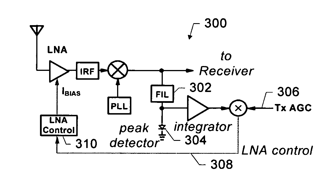
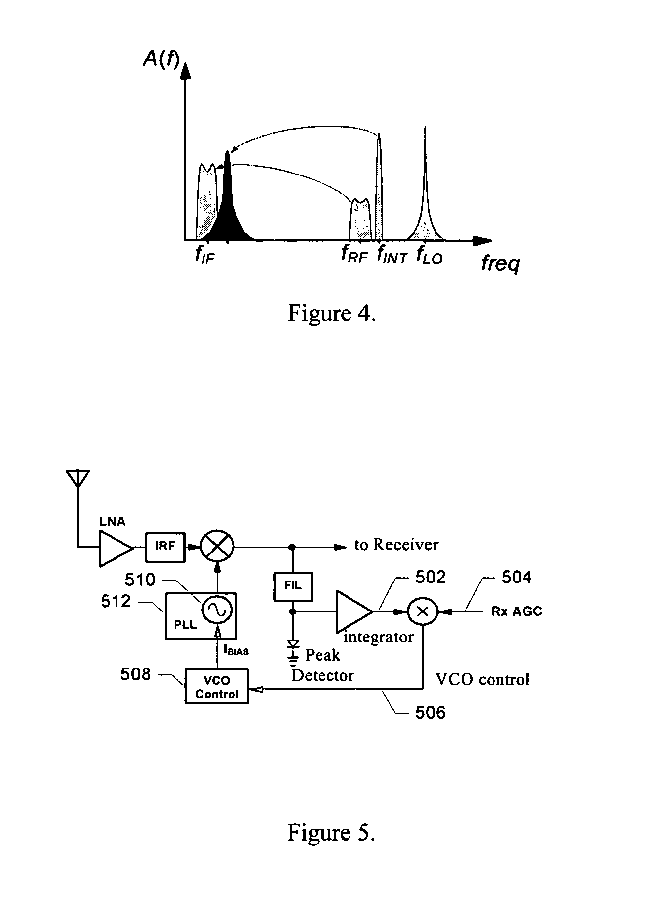
[0007]The present invention includes a system that provides an adaptive receiver that adjusts to the level of interfering signals, minimizing operating current while avoiding problems due to cross modulation, reciprocal mixing, and intermodulation distortion. In one embodiment, the system operates to detect the presence of cross modulation, blocking, or intermodulation distortion in a received signal and adjusts the operating bias of key circuits, including, but not limited to, the LNA, RF down-converting mixer, and VCO.
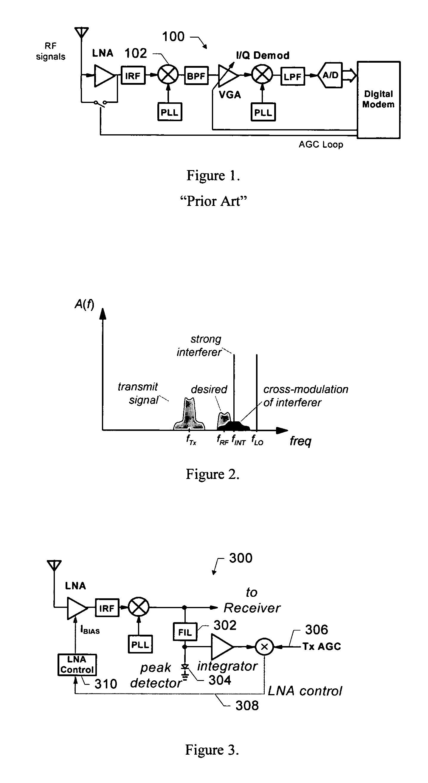
[0010]In another embodiment included in the present invention, a method is provided for providing an adaptive system for use with a radio receiver to adapt to interfering signals associated with a received RF signal. The radio receiver includes an LNA to receive the RF signal and produce an amplified signal that is coupled to a down-converting mixer that produces a mixer output. The method comprises the steps of deriving a peak signal from the mixer output, integrating the peak signal to produce an integrated signal, mixing the integrated signal and a transmit power indicator to produce a current control signal, and controlling a bias current of the LNA with the current control signal, wherein cross modulation associated with the received RF signal is reduced.

Problems solved by technology

But this means key circuits in the radio receiver oftentimes require a high operating bias, even though the likelihood of these difficult situations is low.

Method used


Image

  • Adaptive receiver system that adjusts to the level of interfering signals
  • Adaptive receiver system that adjusts to the level of interfering signals
  • Adaptive receiver system that adjusts to the level of interfering signals

Examples


Embodiment Construction

[0019]The present invention includes a radio receiver system that adjusts the operating bias of key circuits to minimize power consumption but still provides the needed performance. Thus, various embodiments included in the present invention are described in detail in the following text.

[0020]FIG. 2 shows a graph that illustrates the phenomenon of cross modulation in the LNA. This phenomenon—caused by nonlinear operation of the LNA—translates modulation from the transmit signal to an interfering signal. The performance of the radio receiver becomes degraded when the newly-modulated interfering signal overlaps the desired received signal. The linearity of the LNA depends on its operating bias; therefore, a high operating bias is needed to reduce cross modulation.

[0021]Cross modulation depends on the power of the transmit signal and the frequency spectrum of the received signal at the LNA input. The problem surfaces when the received signal (fRX) includes a strong interfering signal (...


PUM


Abstract

Adaptive receiver system that adjusts to the level of interfering signals. An adaptive system is provided for use with a radio receiver to adapt to interfering signals associated with a received RF signal. The radio receiver includes a LNA to receive the RF signal and produce an amplified signal that is coupled to a down-converting mixer that produces a mixer output. A peak detector is coupled to receive the mixer output to produce a peak signal. An integrator is coupled to the peak detector to receive the peak signal and produce an integrated signal and a mixer is coupled to receive the integrated signal and a transmit power indicator to produce a current control signal that is coupled to the LNA. The current control signal is used to control a bias current of the LNA, so that cross modulation associated with the received RF signal is reduced.

Description

CROSS REFERENCE TO RELATED APPLICATIONS[0001]This application claims the benefit of priority from a copending U.S. Provisional Application entitled, “ADAPTIVE RECEIVER THAT ADJUSTS TO THE LEVEL OF INTERFERING SIGNALS” filed on Jan. 16, 2001, and having Application No. 60 / 261,730.FIELD OF THE INVENTION[0002]This invention relates generally to radio receiver systems, and more particularly, to a radio receiver that adapts to the level of interfering signals to improve system performance.BACKGROUND OF THE INVENTION[0003]FIG. 1 shows a diagram of a typical radio receiver 100. The receiver 100 includes a switched-gain low noise amplifier (LNA), a phase-locked loop (PLL) that includes a voltage-controlled oscillator (VCO) and drives a radio frequency down-converting mixer 102, a bandpass filter (BPF), a variable gain amplifier (VGA), an I / Q demodulator, a low pass channel-select filter, and analog to digital (A / D) converter. The radio receiver uses an automatic gain control (AGC) loop to a...

Claims


Application Information

Patent Timeline
IPC IPC(8): H04B1/10H04B1/26
CPCH04B1/109H04B1/26
Inventor GROE, JOHN B.
Owner NXP BV
Learn More