
Method and systems for nesting objects

Inactive Publication Date: 2005-12-27
NESTECH
View PDF4 Cites 40 Cited by
  • Summary
  • Abstract
  • Description
  • Claims
  • Application Information

AI Technical Summary

Benefits of technology

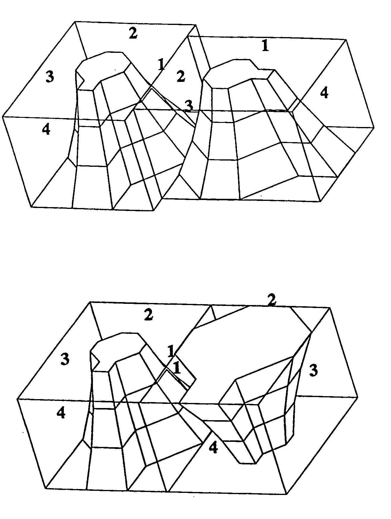
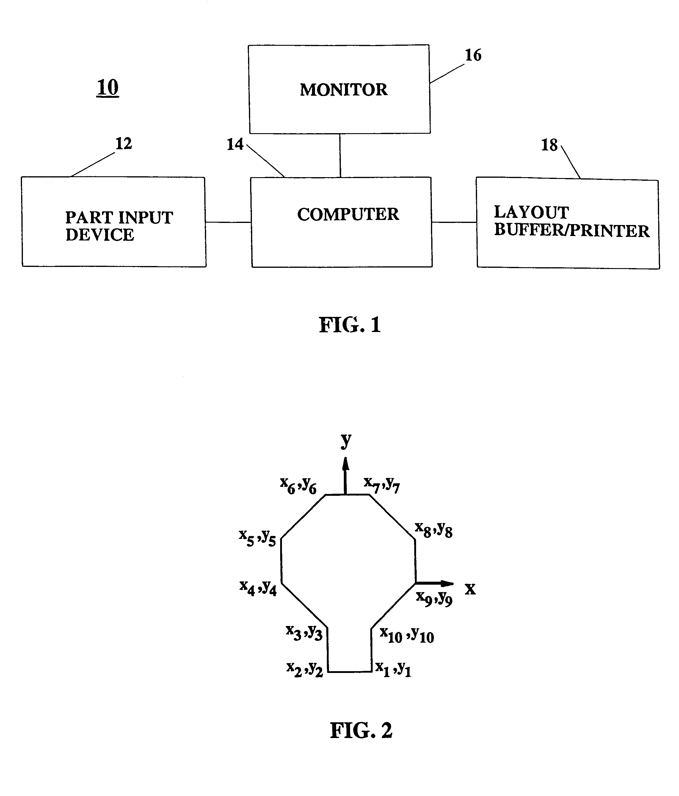
[0008]The invention is a method and system for defining placement of a plurality of two-dimensional objects on a target planar surface with minimal void space between them. The invention automatically packs the maximum number of irregular parts possible (preferably, of up to two different shapes) with minimum wasted surface area. The invention uses a heuristical approach, so that intelligent decisions are made in order to carry only a small percentage of intermediate solutions to completion. In typical cases, this enables the computation time used in the nesting process to be reduced from hours to minutes, allowing for a more interactive nesting design environment.
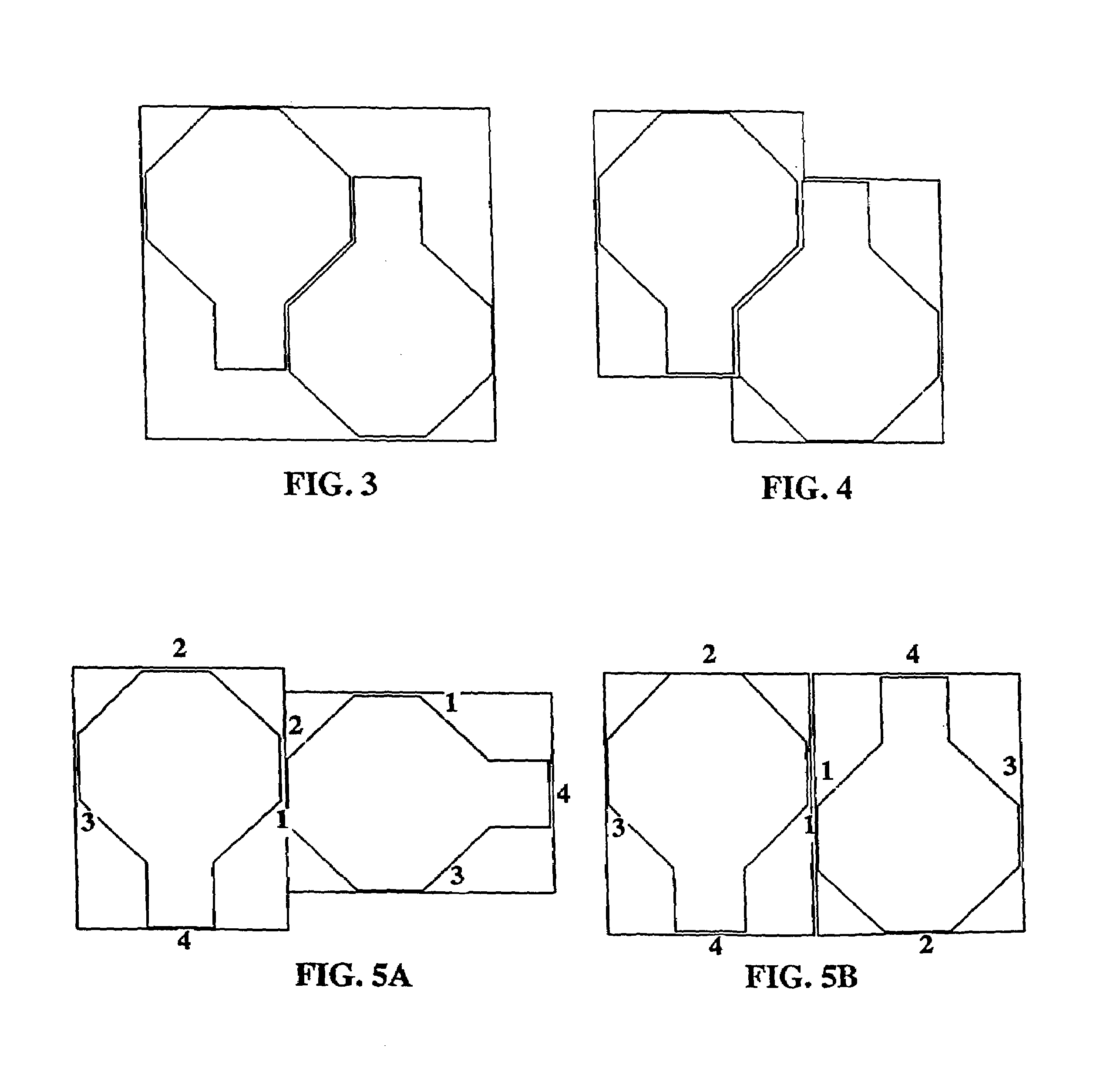
[0009]The invention uses a combination of topology analysis and numerical iteration to determine an efficient layout in short computation times. The process commences by defining a first sub-nest in a central part of the target, grouping parts to each other, and then “grows” or extends outward toward the boundaries of the target. The resultant layouts are generally parallelogramic and thus angled in nature. The “angled” layout is contrary to conventional rectangular (90 degree) nesting practice. A heuristic approach is used with an interactive process to curtail long computation times and to produce nested layouts much faster.
[0010]The nesting method and system of the invention maximizes material utilization from the “center outwards” by minimizing the voids between nested parts. In contrast, conventional nesting practice first defines a target area and then fits parts starting from one edge and “flowing” parts across the target area until the opposite edge is reached.
[0011]The heuristics used to curtail long computation times, are intermediate measures of how good a nest is. As the process proceeds from one stage to the next, measures of nesting effectiveness are calculated and only a small percentage of all the possibilities are allowed to continue to higher stages. This “nest culling” heuristical process is effective in substantially reducing computation times. By allowing only the best intermediate nests to proceed to the “tiling” stages, layout times are typically reduced with no practical loss in nesting efficiency.

Problems solved by technology

The latter cases particularly include shoe manufacture, where the cost of materials, for example cowhides or synthetic materials, is very high.
However, the conventional attempts at such minimization have been relatively ineffective.
A nest constructed in accordance with U.S. Pat. No. 4,210,041 does offer improvement in nesting over prior art techniques; however, the resulting nests are still less than optimal.
Typically three dimensional objects are manually, or by machine, packed in target volumes with less than optimal techniques.
Generally, however, the cubic shape and those container dimension constraints are not present and the conventional packaging methods result in a “filled” container with substantial void regions between the packed objects.

Method used


Image

  • Method and systems for nesting objects
  • Method and systems for nesting objects
  • Method and systems for nesting objects

Examples


example 1

Layout Results Vs Number of Nests / PTiles Kept

[0257]The above defined computer system (FIG. 11) and computer program was implemented for the test object 140 of FIG. 12. The number of nests and ptiles kept for passage to further stages of the computation was varied simultaneously between 5 and 50. That is, these two numbers were varied equally (Nn-pt=Npt-st). A variation from 5 to 50 represents more than two orders of magnitude variation in computation time. The programmed computer produced a layout result for only 5 nests / ptiles kept in less than a minute, whereas it produced a layout for 50 nests / ptile in approximately one hour.

[0258]The test object 140 tested is a very simple one with only a few vertices and cross-section levels to describe it. More complex parts may have typically 10 times more vertices and say 5 times more cross-sections to describe it. This fifty-fold increase in computation time means that for a small number of nests / ptiles kept, the computer processing time w...


PUM


Abstract

The present invention is in the field of manufacturing, processing and design, and also packaging. Nesting is the process of placing objects together with minimal spaces between them. The invention is described below in two forms. The first form, set forth in Part I below, is directed to methods and systems for nesting of two dimensional (2D) objects in a target plane. The second form, set forth in Part II below, is directed to methods and systems for nesting three dimensional (3D) objects in a target volume. The specific details of the preferred embodiments are set forth in those respective parts.

Description

FIELD OF THE INVENTION[0001]The present invention is in the field of manufacturing processing and more particularly relates to methods and systems for nesting of two dimensional objects. Nesting is the process of placing objects together with minimal space between them.BACKGROUND OF THE INVENTION[0002]There are many design and manufacturing processes in which substantially two dimensional parts-to-be-assembled are initially laid out on and then cut from planar or sheet stock. For example, leather shoes, clothing, pocketbooks, and automobile and furniture upholstery are often formed from a plurality of panels, or parts, cut from a cowhide. After cutting of the panels for such an article, conventional seam joining techniques, such as sewing, are used to assemble the panels to form the finished article. Clothing, upholstery and many other articles of other materials are similarly designed and manufactured in a similar manner. Such other articles include body parts for automobiles, for ...

Claims


Application Information

Patent Timeline
IPC IPC(8): G06F17/50
CPCG06F17/5004G06F2217/32G06F2217/42G06F2113/12G06F2113/24G06F30/13
Inventor SADOVNIK, ISAAC
Owner NESTECH
Learn More