Apparatus for manufacturing synthetic resin hollow member incorporating an intermediate element therein

a technology of synthetic resin and intermediate elements, which is applied in the direction of turning machines, turning machine accessories, drawing profiling tools, etc., can solve the problems that manual operation cannot be eliminated, and achieve the effect of high bond strength of joined half bodies, good sealing characteristics and more stably secured

Inactive Publication Date: 2006-01-03
DAIKYONISHIKAWA CORP
View PDF13 Cites 15 Cited by
  • Summary
  • Abstract
  • Description
  • Claims
  • Application Information

AI Technical Summary

Benefits of technology

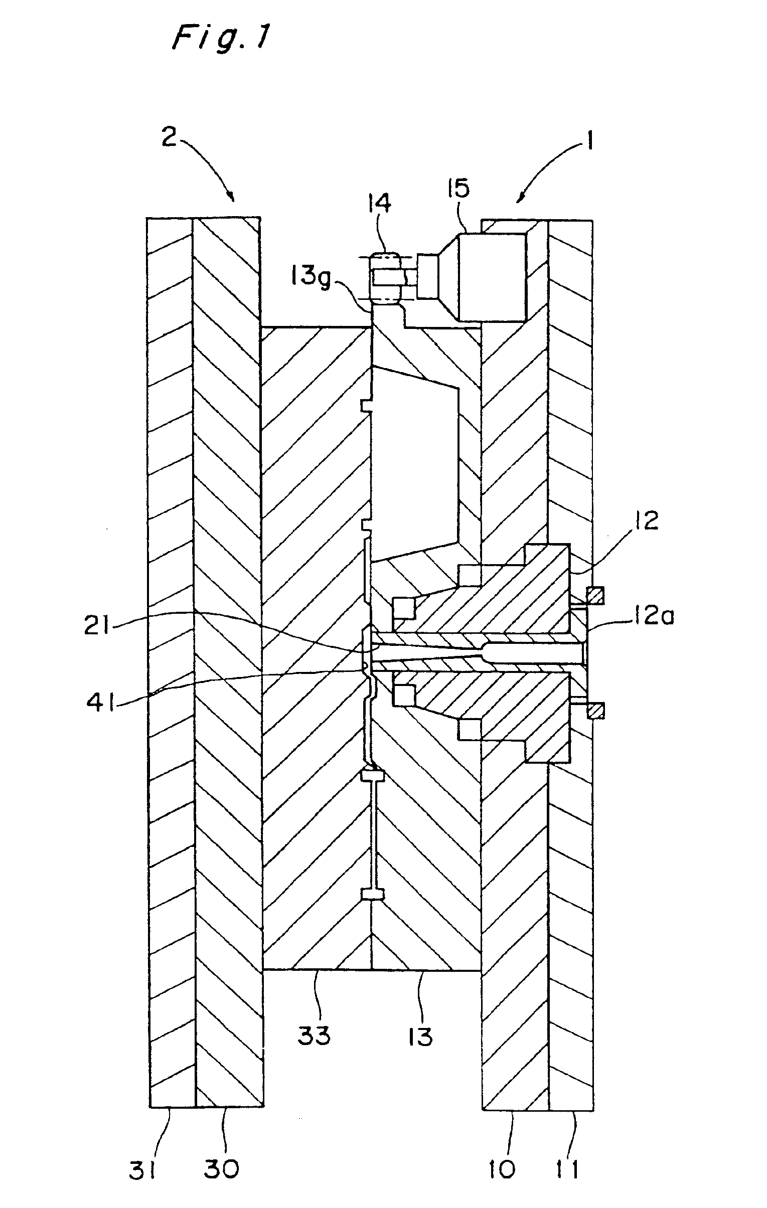
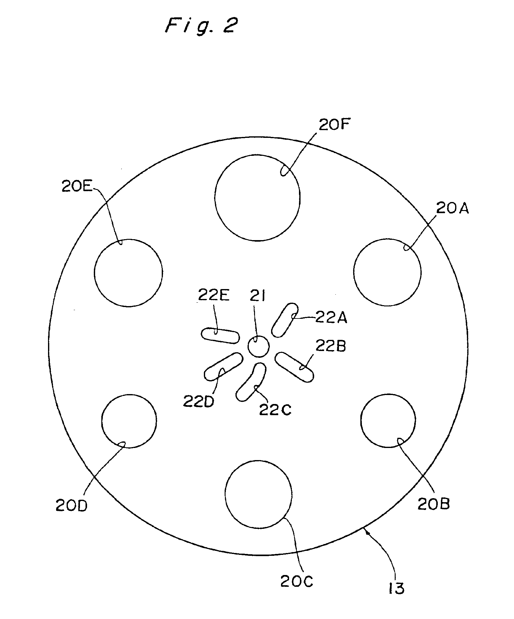
[0020]In the second aspect of the present invention, the apparatus for manufacturing a synthetic resin hollow member comprises a pair of molding dies for rotary injection molding (so-called DRI method) assembled together so as to be opened and closed relative to each other and rotatable over an angle of (360 / 6n) degrees for each turn relative to each other; the molding dies each having a half body molding section consisting of at least one male molding portion and two female molding portions provided in a repetitive sequence of male / female / female in the direction of rotation for each rotational run over an angle of (360 / 3n) degrees, and an intermediate element molding portion provided between specified half body molding portions in the direction of rotational movement for each (360 / 3n) degrees; and wherein for every two rotational runs of the molding dies, a first injection is carried out to mold a first and a second half bodies and an intermediate element to be set between the first and second half bodies, and after the intermediate element is mated to and fitted in the first half body molded at the first injection step, the first half body in which the intermediate element is set is mated to and abutted with a corresponding second half body so that the half bodies are assembled into a molded product, and a second injection is carried out such that melted resin is injected onto the abutting portions of the two half bodies for joining the half bodies together, whereby for every two rotational runs of the molding dies, a hollow member with the intermediate element set between the first and second half bodies can be obtained. Therefore, by employing the DRI method it is possible to carry out the molding and butt-joining of half bodies, and also the molding of an intermediate element in a series of steps. Also it is possible to eliminate such manual work as has been involved in setting the intermediate element in place.
[0021]That is, as compared with the prior art wherein adhesive bonding or heat melting is carried out for joining separate half bodies, high bond strength of joined half bodies and good sealing characteristics of the butt-joined surface can be more stably secured; and by using the DRI method it is possible to achieve higher production efficiency.

Problems solved by technology

This involves a problem that a stage for manufacturing an intermediate element structure must be provided separately from the stage for abutting and joining the half bodies together, and also, it means that the need for troublesome manual operation cannot be eliminated.

Method used


Image

  • Apparatus for manufacturing synthetic resin hollow member incorporating an intermediate element therein
  • Apparatus for manufacturing synthetic resin hollow member incorporating an intermediate element therein
  • Apparatus for manufacturing synthetic resin hollow member incorporating an intermediate element therein

Examples


Embodiment Construction

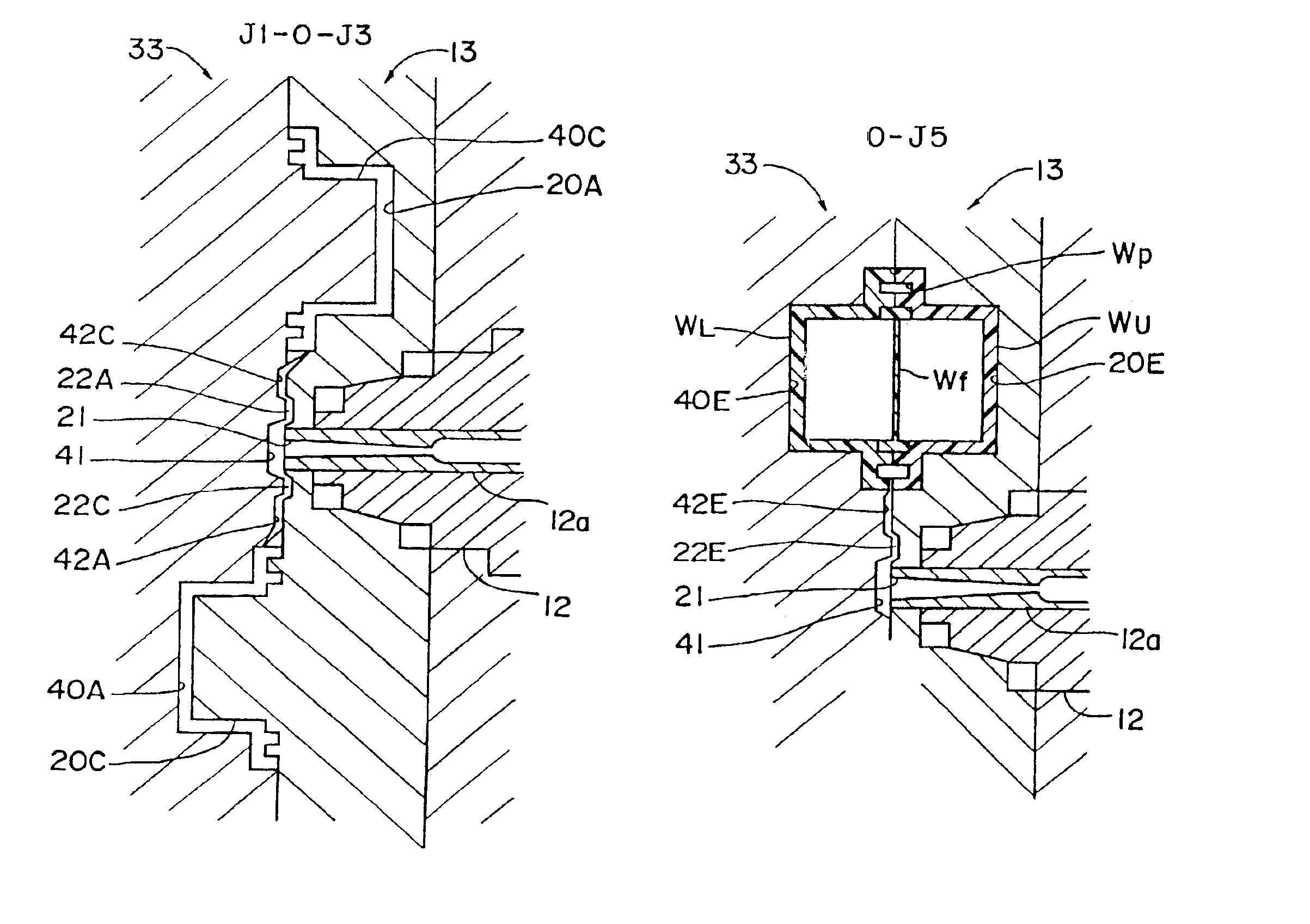
[0057]One embodiment of the present invention will now be described in detail with reference to the accompanying drawings which illustrate by way of example the embodiment as applied to the manufacturing of a synthetic resin-made oil strainer.

[0058]FIGS. 28 through 31 show an oil strainer W as a synthetic resin hollow member embodying the invention. The oil strainer W is a hollow member comprising an upper half body WU having an outlet tube portion Wo, and a lower half body WL having an inlet tube portion Wi, and has a filter Wf (see FIG. 31) disposed in a hollow interior thereof for filtering foreign matter present in incoming oil.

[0059]The oil strainer W, as will be described in detail hereinafter, is a product manufactured in the form of a hollow member incorporating an intermediate element (filter Wf) by the so-called die rotary injection (DRI) method such that upper and lower half bodies WU, WL, and a filter Wf as the intermediate element to be disposed in the hollow member are...


PUM

PropertyMeasurementUnit
angleaaaaaaaaaa
angleaaaaaaaaaa
angleaaaaaaaaaa

Abstract

Method and apparatus for manufacturing a synthetic resin-made hollow member incorporating an intermediate element are provided which enable operations of molding half bodies, abutting and joining the half bodies together, and molding an intermediate element in a series of steps, and which eliminate the necessity of such a manual work as may otherwise be required in incorporating the intermediate element into the half bodies. A pair of rotary injection molding dies are used which can be opened and closed relative to each other and are rotatable relative to each other over an angle of 60° for each turn, each die having a half body molding section including one male molding portion and two female molding portions in the direction of rotation for each rotational run over an angle of 120°, each die also having an intermediate element molding portion provided between specified half body molding portions in the direction of each rotational run over an angle of 120°. In each two rotational runs of the molding dies, a series of steps is carried out including first injection for molding a pair of half bodies and an intermediate element, molded product setting for matching two half bodies with the intermediate element set in place and abutting the two half bodies against each other, and second injection for injecting melted resin onto the abutting portions and joining the two half bodies, whereby a hollow member with the intermediate element set between the two half bodies can be obtained.

Description

[0001]This is a Divisional Application of application Ser. No. 09 / 189,150, filed Nov. 10, 1998, now U.S. Pat. No. 6,299,816.BACKGROUND OF THE INVENTION[0002]The present invention relates to a method and apparatus for manufacturing a synthetic resin hollow member incorporating an intermediate element therein, for example, a synthetic resin-made strainer having a filter incorporated therein, and to such a synthetic resin hollow member.[0003]Conventionally, when manufacturing such a synthetic resin hollow item incorporating an intermediate element therein, for example, a synthetic resin-made strainer having a filter incorporated therein, one generally known method which would be commonly considered is such that with a pair of synthetic resin-made half bodies previously molded which constitute a pair of shells of the hollow member, a separately manufactured intermediate element is disposed between the two half bodies, the two half bodies being then brought into abutment against each oth...

Claims


Application Information

Patent Timeline
Patent Type & Authority Patents(United States)
IPC IPC(8): B29C45/14B29C45/26B29C45/00B29K105/20
CPCB29C45/0062B29C2045/0067B29C66/54
Inventor TAKEMOTO, YOSHIHIRONISHIDA, SHOSO
Owner DAIKYONISHIKAWA CORP
Why Eureka
Try Eureka