Method and apparatus for using an alignment target with designed in offset

Inactive Publication Date: 2006-01-03
ONTO INNOVATION INC
View PDF97 Cites 209 Cited by
  • Summary
  • Abstract
  • Description
  • Claims
  • Application Information

AI Technical Summary

Benefits of technology

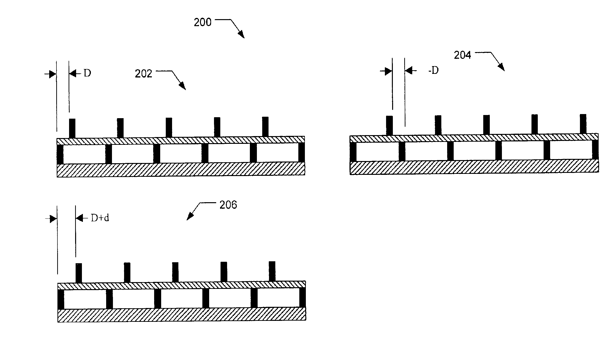
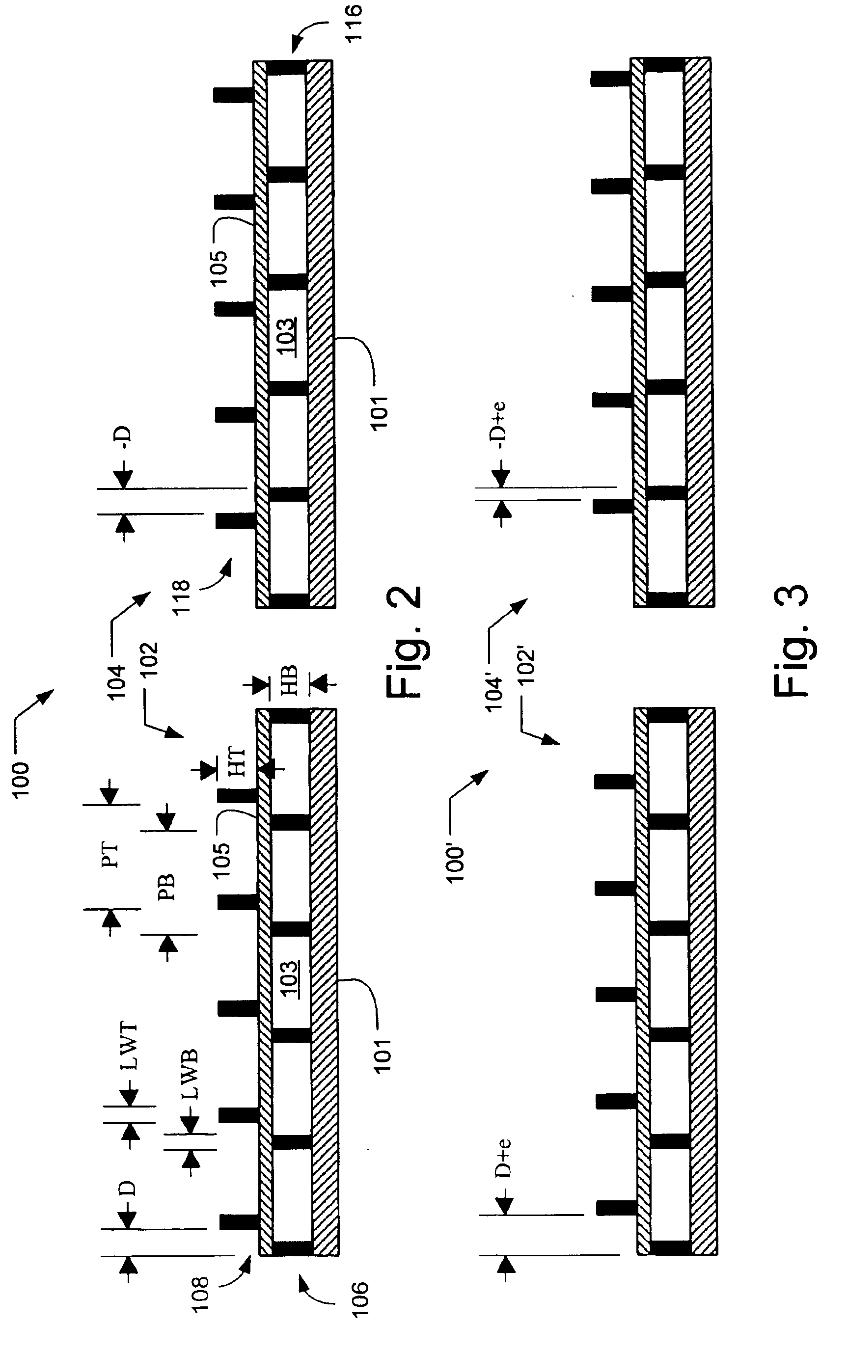
[0009]In accordance with the present invention, an alignment target includes periodic patterns on two elements, such as layers on a substrate. The alignment target includes at least two locations at least one of which includes a designed in offset. In one embodiment, the two locations both have designed in offsets of equal magnitude and opposite directions. For example, two separate overlay patterns that are mirror images of each other may be used. Alternatively, a single overlay pattern that includes periodic patterns with different pitches may be used. In such an embodiment, the length of the pattern is sufficient to allow two locations that have a designed in offset of the same magnitude but opposite direction. To determine the alignment error between the two elements, the alignment target is illuminated at two locations and resulting

Problems solved by technology

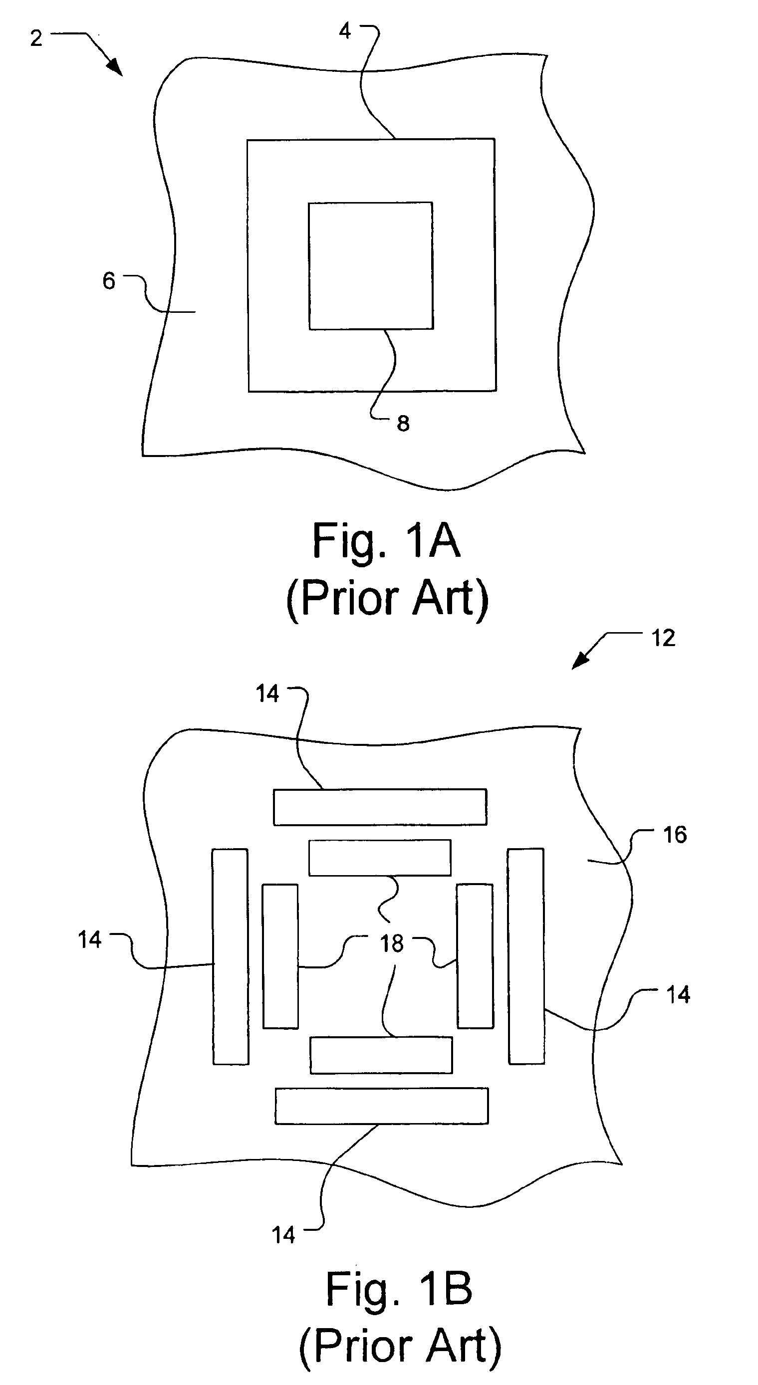
However, as the integrated circuit feature sizes continue to decrease to provide increasing circuit density, it becomes increasingly difficult to measure the alignment accuracy of one masking level to the previous level.
This overlay metrology problem becomes particularly difficult at submicrometer feature sizes where overlay alignment tolerances are reduced to provide reliable semiconductor devices.
Conventional imaging devices, unfortunately, suffer from disadvantages such as sensitivity to vibration and cost.
Moreover, conven

Method used


Image

  • Method and apparatus for using an alignment target with designed in offset
  • Method and apparatus for using an alignment target with designed in offset
  • Method and apparatus for using an alignment target with designed in offset

Examples


Embodiment Construction

[0058]In accordance with an embodiment of the present invention, the alignment of two elements, e.g., two layers on a substrate or any other two elements, is measured using an alignment target having at least one periodic pattern on one element and at least one periodic pattern on the other element. The alignment of the two elements may be determined by measuring the alignment of the at least two periodic patterns. The alignment target includes at least two locations, at least one of which has a designed in offsets between the periodic patterns on each element. The designed in offset is an offset between the periodic pattern on the first element and the periodic pattern on the second element such that when the two elements are aligned, there will be an offset between the periodic patterns. In one embodiment, both measurement locations on the alignment target will have a designed in offset of equal magnitude and opposite direction. In other embodiments, the designed in offsets at the...


PUM


Abstract

An alignment target includes periodic patterns on two elements. The alignment target includes two locations, at least one of which has a designed in offset. In one embodiment, both measurement locations have a designed in offset of the same magnitude but opposite directions. For example, two separate overlay patterns that are mirror images of each other may be used. Alternatively, the magnitudes and/or directions may vary between the measurement locations. The radiation that interacts with the measurement locations is compared. The calculated difference is extremely sensitive to any alignment error. If the difference between the patterns is approximately zero, the elements are properly aligned. When an alignment error is introduced, however, calculated difference can be used to determine the error. In one embodiment, the alignment target is modeled to determine the alignment error. In another embodiment, additional overlay patterns with additional reference offsets are used to determine the alignment error.

Description

BACKGROUND OF THE INVENTION[0001]1. Field of the Invention[0002]The present invention relates to alignment metrology, and in particular to an alignment target and method of use that includes two locations with designed in offsets.[0003]2. Discussion of the Related Art[0004]Semiconductor processing for forming integrated circuits requires a series of processing steps. These processing steps include the deposition and patterning of material layers such as insulating layers, polysilicon layers, and metal layers. The material layers are typically patterned using a photoresist layer that is patterned over the material layer using a photomask or reticle. Typically the photomask has alignment targets or keys that are aligned to fiduciary marks formed in the previous layer on the substrate. However, as the integrated circuit feature sizes continue to decrease to provide increasing circuit density, it becomes increasingly difficult to measure the alignment accuracy of one masking level to th...

Claims


Application Information

Patent Timeline
IPC IPC(8): G01B11/27
CPCG03F9/7076G03F7/70633H01L21/681
Inventor YANG, WEIDONGLOWE-WEBB, ROGER R.HEATON, JOHN D.LI, GUOGUANG
Owner ONTO INNOVATION INC
Why Eureka
Try Eureka